2 led indicators (d1-d6), 3 external power connector (+48v) (j2), 4 surge/shield ground connector (j4) – Varec TankGate Interface 8315 Series User Manual
Page 27: 5 field wiring terminal block (j3)
8315 TGI
8215 L&J Tankway Communications Interface Module
Varec, Inc.
17
3.2.2
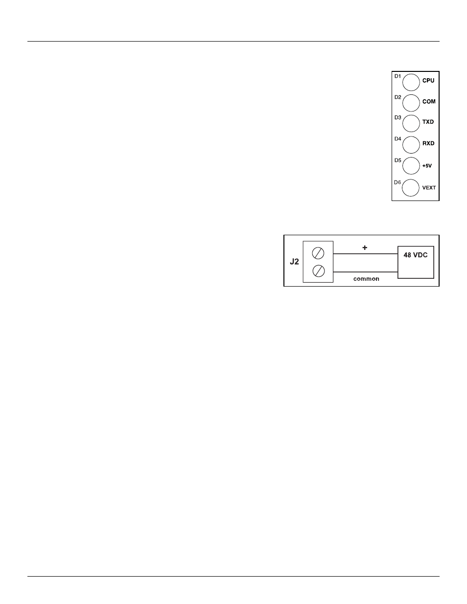
LED Indicators (D1-D6)
The LED displays indicate the status of the Model 8315’s CPU and
communications. The indicators are identified in the following figure.
•
CPU: CPU activity
•
COM: Communication between the TankGate and the host computer
•
TXD: Transmitting data to tank gauge
•
RXD: Receiving data from tank gauge
•
+5V: Indicates interface module power
•
+VEXT: Indicates external power
Figure 3-2: LED Indicators
3.2.3
External Power Connector (+48V) (J2)
Connect the +48 VDC External Power as shown
below:
Figure 3-3: External Power Connector
3.2.4
Surge/Shield Ground Connector (J4)
Connecting the Surge/Shield ground connector
Caution! This ground connection is important for system safety.
•
Connect a 14 AWG copper wire between the ground terminal (J4) and a good earth ground.
Perform this step before connecting ANY other wires.
•
Verify that the resistance in this connection does not exceed 1 ohm.
3.2.5
Field Wiring terminal block (J3)
A schematic illustrating the terminal connections of the Model 8315 is shown below: