6 interrupt input function, 7 pulse output function, Interrupt input function – Toshiba Programmable Logic Controller V200 User Manual
Page 102: Pulse output function
Page 94
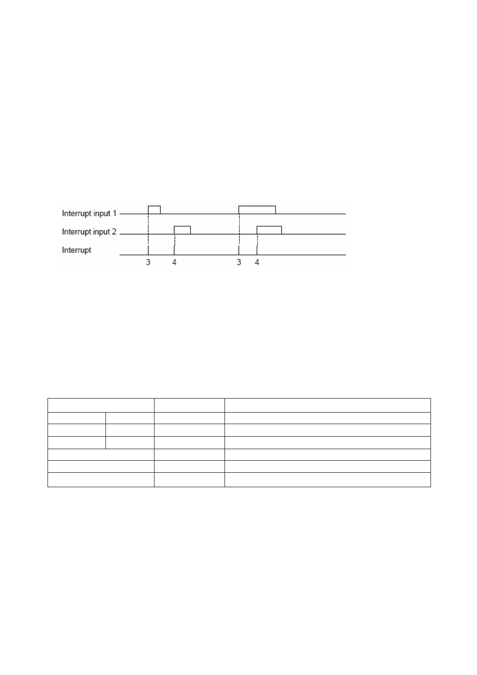
5.6 Interrupt Input Function
When the signal state of the interrupt input is changed from OFF to ON (or ON to OFF), the corresponding I/O
interrupt program is activated immediately. Up to 2 interrupt inputs can be used. The interrupt generation condition
can be selected either rising edge (OFF to ON) or falling edge (ON to OFF) for each input. The I/O interrupt program
#1 is corresponding to the interrupt input 1, and the I/O interrupt program #2 is corresponding to the interrupt input 2.
Hardware condition
Interrupt input (IP 1 and IP 2)
ON/OFF pulse width: 100 microsec. or more
Interrupt assignment
Interrupt input 1 — I/O interrupt program #1
Interrupt input 2 — I/O interrupt program #2
5.7 Pulse Output Function
There are two transistor outputs Y0 and Y1 and can be used for pulse output.
When CW/CCW mode is selected if frequency is positive, match output 1 will be selected so that pulses will be out
on Y0 and if frequency is negative match output 2 will be selected so that pulses will be out on Y1.
In PULSE/DIR mode the pulses will be out on Y0 i.e. Match output1. If the frequency is negative then direction pin
can be set to high through Match output 2.
Function
Register/device
Remarks
CW/ CCW
PLS/DIR
CW Pulse
PLS
Y0
CCW Pulse
DIR
Y1
Pulse enable flag
M336
Output is enabled when ON
Frequency setting register
MW22 MW23
Data range: -5000 to –50, 50 to 5000
Frequency setting error flag
M191
ON at error (Reset OFF automatically)