Toshiba Programmable Logic Controller V200 User Manual
Page 101
Page 93
The function selection is done through configuration register1
Function
Register/device
Remarks
Phase A
IP 1 (X000)
Phase B
IP 2 (X001)
Reset input
IP 3 (X002)
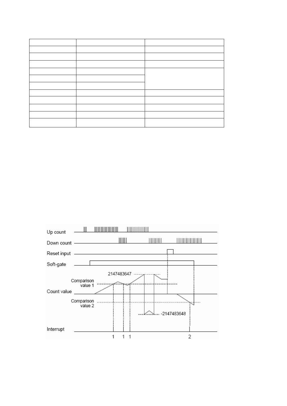
Comparison value 1
MW12 MW13
Data range: 0 to 4294967295
Comparison value 2
MW14 MW15
Count value
MW16 MW17
Soft-gate
M320
Operation is enabled when ON
Interrupt enable 1
M322
Interrupt 1 is enabled when ON
Count preset 1
M324
Used to preset the count value
Interrupt enable 2
M323
Interrupt 2 is enabled when ON
Count preset 2
M325
Used to preset the count value
Hardware condition:
Phase A and phase B (IP 1 and IP 2)
1X Mode
ON/OFF pulse width: 100 micro sec. or more (max. 5 kHz)
2X Mode
ON/OFF pulse width: 100 micro sec. or more (max. 5 kHz)
4X Mode
ON/OFF pulse width: 100 micro sec. or more (max. 5 kHz)
Reset input (IP3)
ON/OFF duration: 2 ms or more
Interrupt assignment:
Comparison value 1 — I/O interrupt program #1
Comparison value 2 — I/O interrupt program #2