Toshiba G7 User Manual
Page 77
G7 ASD Multi-Protocol Communication Option and PG Feedback Option Manual
70
Bit-mapped drive option command word. Table 10 on page 23 provides the format of this command
word.
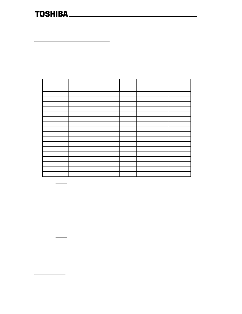
F831 Command Data / F832 Command Data
Via ASD parameters F831 and F832, the user has the ability to select two additional high-speed scan
command items to be written to the ASD. Table 27 provides a list of the available command scan data
selections. The “Parameter” column indicates the drive’s internal parameter to which the corresponding
selection is mapped. Once selected, the corresponding command data for the selected scan items can be
written to the drive via AC/DC drive object attributes #102 and #103.
Table 27: Drive Command Scan Data
F831
∼∼∼∼F835
Setting
Description Unit
Range
ASD
Parameter
0 No
selection
-
-
0xFFFF
1 RESERVED
-
-
-
2 RESERVED
-
-
-
3
Incremental speed reference
0.01Hz
0 ~ 500
0xFA08
4
Absolute torque limit
0.01%
0 ~ 25000
0xFA34
5
Positive torque limit
0.01%
0 ~ 25000
0x0441
6
Negative torque limit
0.01%
0 ~ 25000
0x0443
7
Torque command
0.01%
-25000 ~ 25000
0xFA33
8
Speed torque bias
0.01%
-25000 ~ 25000
0x0726
9
Tension torque bias
0.01%
-25000 ~ 25000
0x0727
10
Load balance gain
0.01
0 ~25000
0x0728
11
Drooping gain
0.01
0 ~ 10000
0x0320
12
Speed loop proportional gain
0.1
32 ~ 10000
0x0376
13
Speed loop integral gain
0.1
100 ~ 2000
0x0377
14 Output
terminals
-
-
0xFA50
15
Load moment of inertia
0.0001
100 ~ 10000
0xFA35
16 Extended
command
-
-
0xFA23
Note 1: Items marked as “RESERVED” in Table 27 are reserved for future use. Selecting
one of the corresponding values as command scan data will have no effect on drive
operation.
Note 2: Although not disallowed, avoid configuring both scan command data parametes
F831 and F832 with the same command data selection (for example, do not set both F831
and F832 to “3”, etc.). Unexpected drive behavior could result if different data values
are written to the corresponding command locations.
Note 3: Parameters F831 and F832 are only validated on drive reset or power-up.
Therefore, if either of these parameters is changed, be sure to reset the drive to validate
the changes.
Note 4: Data range checking is not performed on command scan items. If a value outside
of a specific item’s valid range is written to the attribute (either via explicit messaging or
an I/O assembly object), that value will be accepted by the Multicom interface, but
ignored by the drive.
Item #16 in Table 27 (extended command) is a bit-mapped drive command word internally located at
parameter 0xFA23. Table 11 on page 23 provides the format of this extended command word.
Output Frequency
Unsigned 16-bit value whose value is the current ASD operating frequency multiplied by 100. For
example, if the ASD is currently running at 55.34Hz, then this attribute will be 55.34 x 100 = 5534
10
(0x159E).