Adjustment mode setting flow chart, P. 67) – TOA Electronics A-9120DH User Manual
Page 67
67
A D J U S T
Input gain settings
D U C K E R
D E P T H
– 2 0
Ducker attenuation level setting
(For the channel on which the D-001T is used)
(For the channel on which the AN-001T is not used)
B A S S
+ 1 2
T R E B L E
– 1 0
L O U D N E S S –
O N
EQ ON/OFF, Band number, Gain, Q,
and Center frequency settings
C O M P R E S S O R –
O F F
V O X S E N S I T I V I T Y
– 3 0
VOX (Voice Operated Exchange) setting
E Q
1 0
+ 1 2
0 7
3 1 5
.
.
EQ ON/OFF, Band number, Gain, Q,
and Center frequency settings
E Q
1 0
+ 1 2
0 7
3 1 5
.
.
H P F –
4 0 0
H Z
L P F –
1 2 5
.
Output channel selection
and
Output gain settings
Output channel selection and Output gain setting
B A S S
+ 1 2
T R E B L E
– 1 0
L O U D N E S S –
O N
C O M P R E S S O R –
O F F
H P F –
4 0 0
H Z
L P F –
1 2 5
.
S P
E Q
A L L
F L A T
I N 1 – I N 1
O N
0 0
.
:
O U T 1
– O U T 1
O N
0 0
.
:
Setting menu screen
Note
Press the Enter key
to confirm this setting.
I N P U T
0 1
O N
E V E N T
0 1
– R O U T E
O N
(Normal matrix operation)
(1-channel or 2-channel output operation)
(For the channel on which the AN-001T is used and the ANC operation is set to ACTIVE)
Lowest output level setting
S A M P L E
T I M E
2 0
G A I N R A T I O
3 : 3
Reference level adjustment
A N C
A D J
0
: S E N S
8
M I N I M U M
L E V E L
–
6
M A X I M U M
L E V E L
0
Highest output level setting
Note
The selectable output channel in the 1-channel
output operation method is OUTPUT 1 only.
UTILITY
MEMORY
Normal use state
PARAMETER
Press for over 2 seconds.
To turn on,
ON/OFF
To turn on,
ON/OFF
To select,
PARAMETER
To select,
PARAMETER
To select,
INPUT VOLUME
To select,
OUTPUT SEL
To select,
OUTPUT VOLIME
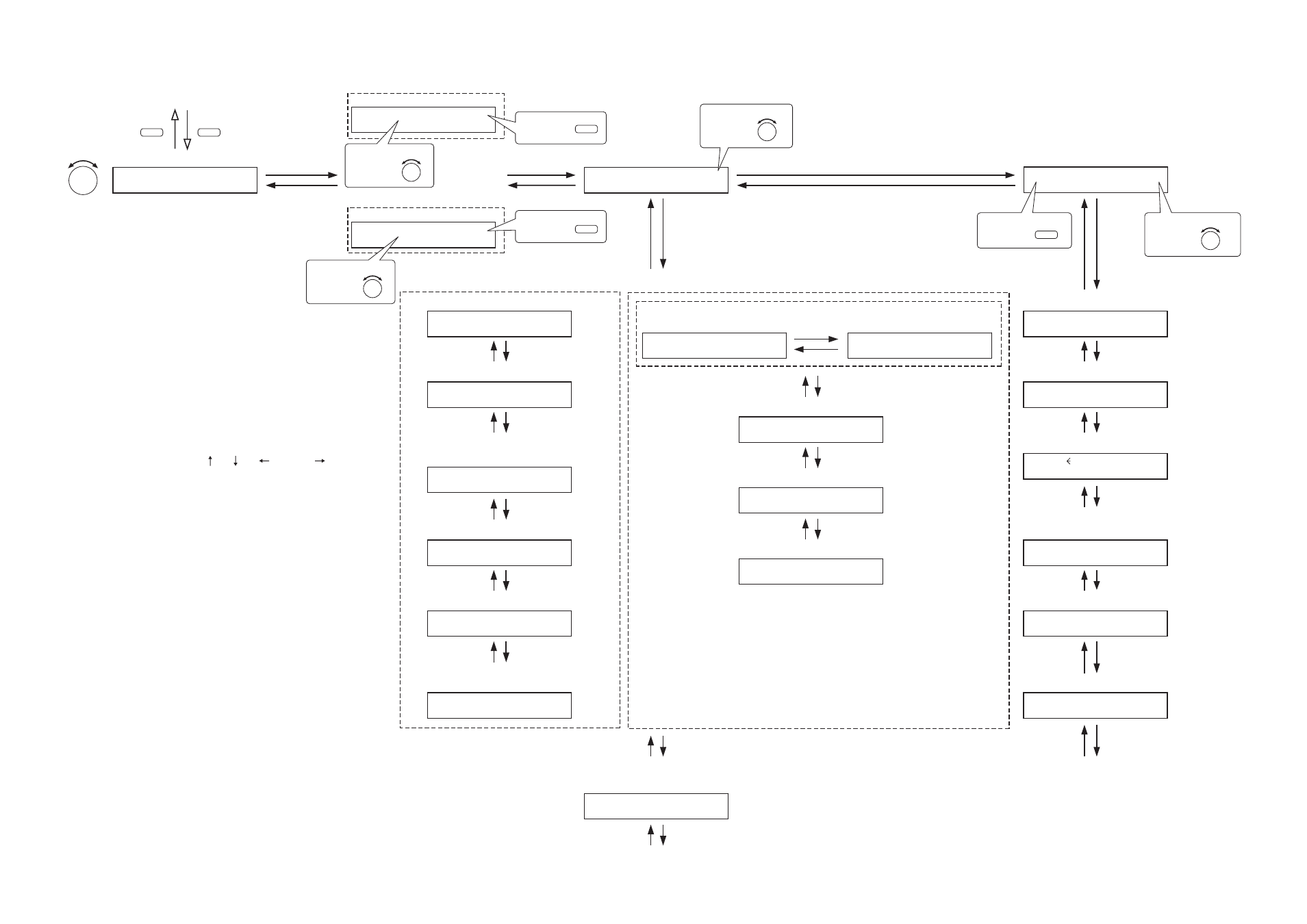
13.8.2. Adjustment mode setting flow chart
The screen display examples shown at right may differ from
actual displays.
The on-screen indications shown in red here (actually shown by
flashing cursors) are parameters or setting contents to be
selected with the Parameter setting knob, input channel
selection key or other designated keys.
ÇsThe indications of the [ ], [ ], [
], and [
] arrows
represent that the screen is switched with the Screen shift key.
Unless otherwise specified, use the Parameter setting knob for
each parameter selection.