Utility setting, Setting flow chart, Set the utility function. (refer to – TOA Electronics A-9120DH User Manual
Page 51: P. 51, P. 51)
51
U T I L I T Y – S E T T I N G
U T I L I T Y
C - I N
Function selection
(when the control input is selected)
Control input number selection
Control input function setting
Control input function setting
C - I N 0 1
E V E N T
N O N E
Event assignment display
(Only in the normal matrix operation)
(When the control input function
is set to VOLUP)
Volume increasing level setting
(When the control input function
is set to VOLDOWN)
Volume decreasing level setting
(When the control input function
is set to MUTE)
(When the control input function
is set to POWER)
Channel number selection
(When the control input function
is set to EMG-MUTE)
C - I N 0 1
–
N O N E
Control input function setting
C - I N 0 1 –
N O N E
C - I N 0 1 –
V O L U P
C - I N 0 1 –
M U T E
C - I N 0 1 – V O L U P
0 5
.
C - I N 0 1 – V O L U P
I N 1
C - I N 0 1 –
E M G - M U T E
C - I N 0 1 –
P O W E R
C - I N 0 1 – M U T E
I N 1
C - I N 0 1 – V O L D W N
0 5
.
Setting menu screen
C - I N 0 1 – V O L D W N
I N 1
C - I N 0 1 –
V O L D O W N
Channel number selection
C - I N 0 1 –
C O U T 0 1
C - I N 0 1 – S Y N C
O N
Interlock output control setting
Interlock output terminal setting
(When the interlock output control is ON)
Control input function setting
Interlock output control setting
C - I N 0 1 –
C O U T 0 1
Interlock output terminal setting
(When the interlock output control is ON)
C - I N 0 1 – S Y N C
O N
Control input function setting
(Only in the 1-channel or 2-channel
output operation, when the control
input terminal is set to BGMEND)
C - I N 0 1 –
B G M E N D
UTILITY
MEMORY
Normal use state
Press for over 2 seconds.
PARAMETER
or
PARAMETER
PARAMETER
PARAMETER
PARAMETER
PARAMETER
PARAMETER
PARAMETER
Channel number selection
(When the control input function
is set to VOLUP or VOLDOWN)
To select,
or
INPUT SELECT
1 – 8
OUTPUT SEL
To select,
or
INPUT SELECT
1 – 8
OUTPUT SEL
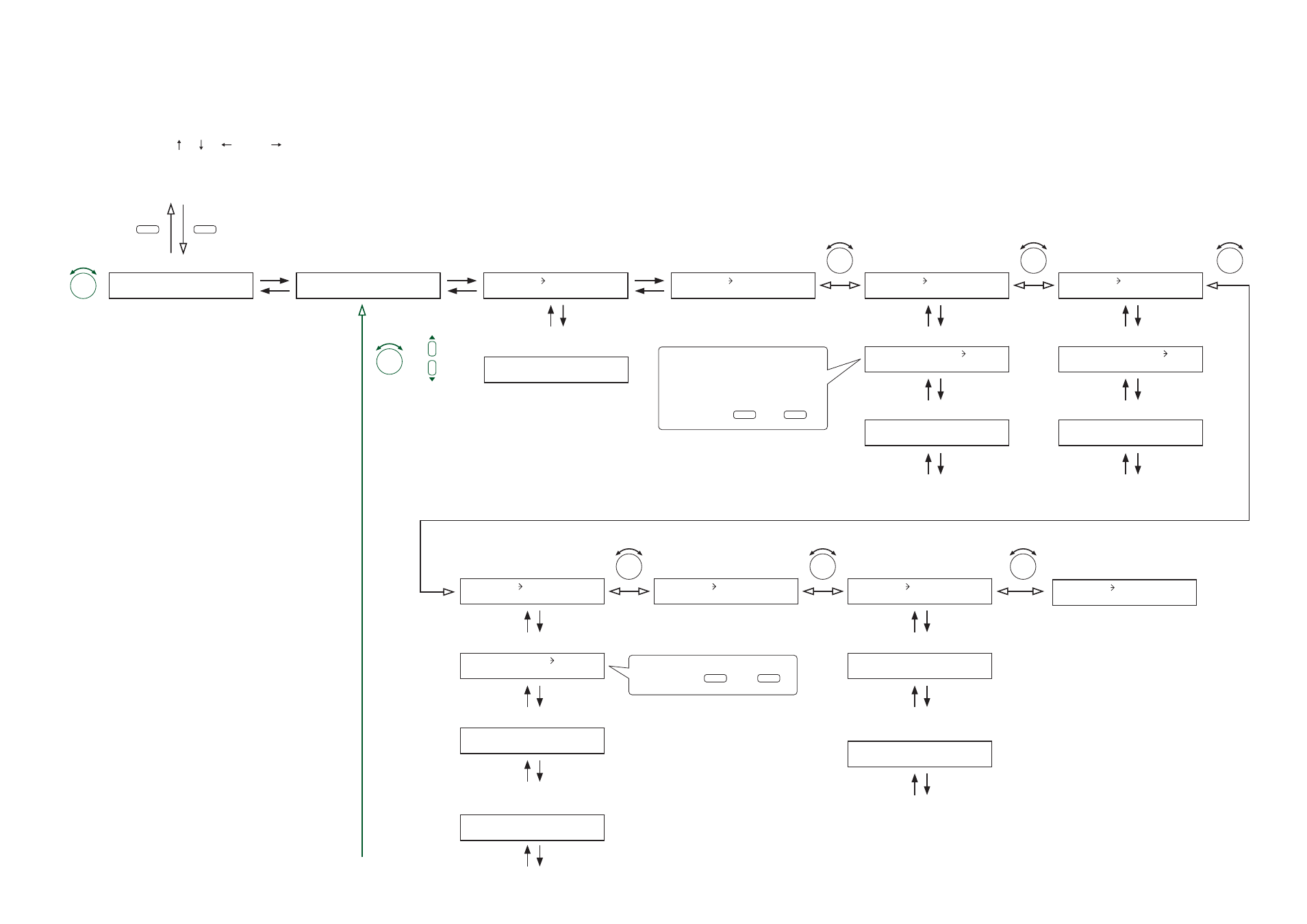
13.7.1. Setting flow chart
The screen display examples shown below may differ from actual displays.
The on-screen indications shown in red here (actually shown by flashing cursors) are parameters or setting
contents to be selected with the Parameter setting knob, input channel selection key or other designated keys.
The indications of the [ ], [ ], [
], and [
] arrows represent that the screen is switched with the Screen
shift key.
Unless otherwise specified, use the Parameter setting knob for each parameter selection.
13.7. Utility Setting
Note
When the 1-channel output operation is selected for the operation method, only
Output channel 1 can be set. No setting screens for Output channel 2 appear.