Appendix e – Omron NT-series Programmable Terminal V022-E3-1 User Manual
Page 285
Note
1
6
9
5
. .( $0&
Appendix E
Connecting an NT600S to a C Series C200HS, C200HX/HG/HE, or CPM1, CQM1, CVM1/CV Series (-V
) CPU
Unit (Including Communication Port)
C-Series C200HS, C200HX/HG/HE, CPM1, CQM1, CVM1/CV-Series (-EV
) CPU Unit 9-pin Connector Specifi-
cations
Applicable CPU:
C200HS-CPU21-E
C200HE-CPU32-E
C200HG-CPU33-E
C200HX-CPU34-E
C200HS-CPU23-E
C200HE-CPU42-E
C200HG-CPU43-E
C200HX-CPU44-E
C200HS-CPU31-E
C200HG-CPU53-E
C200HX-CPU54-E
C200HS-CPU33-E
C200HG-CPU63-E
C200HX-CPU64-E
CPM1-10CDR-
CQM1-CPU21-E
CV500-CPU01-EV1
CPM1-20CDR-
CQM1-CPU41-E
CV1000-CPU01-EV1
CPM1-30CDR-
CQM1-CPU42-E
CV2000-CPU01-EV1
CQM1-CPU43-E
CVM1-CPU01-EV
CQM1-CPU44-E
CVM1-CPU11-EV
CVM1-CPU21-EV
The host link function incorporated in CV/CVM1 CPUs (with the exception of
-EV
) cannot be used.
Electrical characteristics:
Complies with EIA RS-232C
Signal direction:
Signal input and output is relative to the PC.
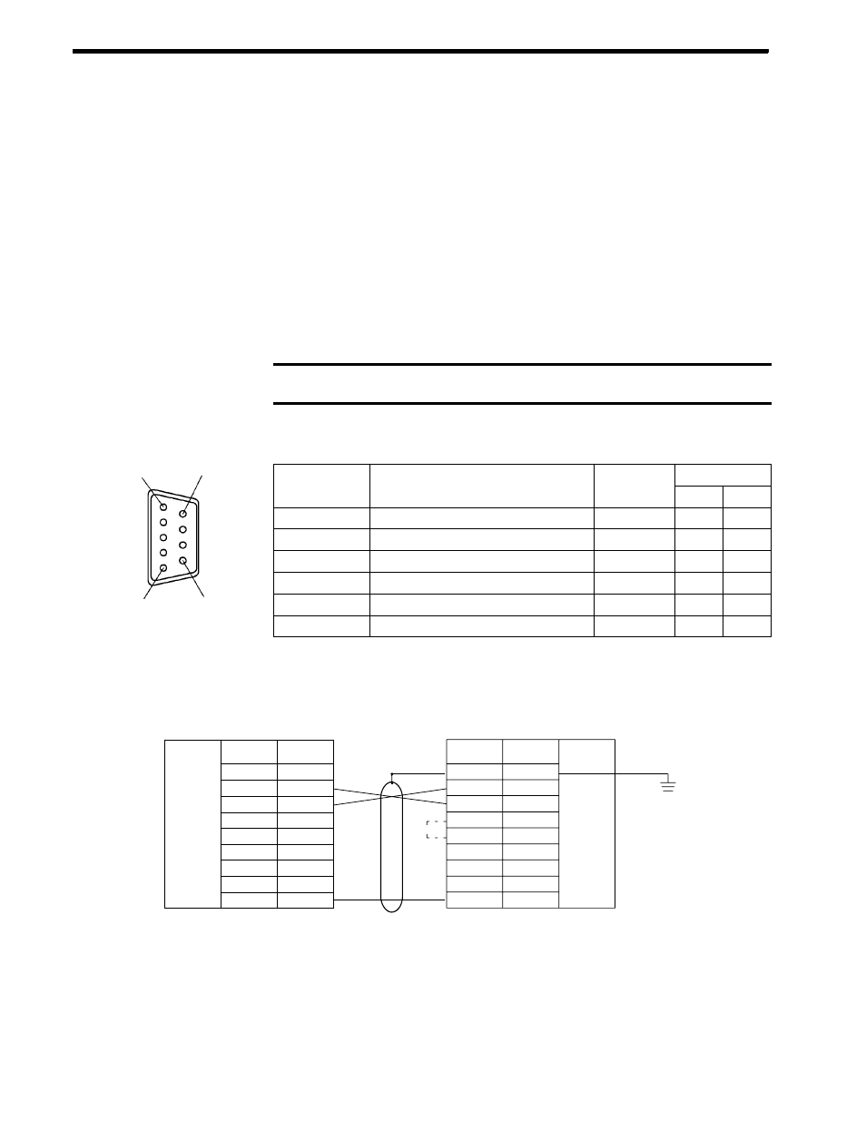
Connector
Signal Name
Abbreviation
Signal Direction
Connector
Pin No.
Signal Name
Abbreviation
Input
Output
Connector cover
Frame ground
FG
--
--
2
Send data
SD (TXD)
3
Receive data
RD (RXD)
4
Request to send
RS (RTS)
5
Clear to send
CS (CTS)
9
Signal ground
SG (GND)
--
--
Wiring Connections
The NT600S does not use pin 4 (RS) or pin 5 (CS). Either short the RS and CS pins of the PC connector together
or set the CTS setting selector switch at the rear face of the host link unit to “0V” (see
in the figure).
1
2
3
4
5
6
7
8
9
Pin
number
Abbrevi-
atioon
FG
SD
RD
RS
CS
+5V
--
--
SG
RS-232C
interface
Shielding
wire
NT600S
PC (host link unit)
RS-232C
interface
Pin
number
Abbrevi-
atioon
2
3
4
5
--
--
--
9
FG
SD
RD
RS
CS
--
--
--
SG
9-pin connector
Connector cover