Attaching the phase contrast optical elements – Olympus IX81 User Manual
Page 34
29
With the IX-ULWCD Condenser
(Note) The IX-PHCU or IX-PH1U can be attached only in the Ph1 and PhC positions.
Do not remove the built-in elements.
Optical Element
Indication
Applicable Objectives
PHL (Built in)
PhL
UPlanFl4XPh
IX-PHCU
Ph1
CPlan10XPh, LCAch20XPh, CPlanFl10XPh
IX-PH1U
PhC
UPlanFl10XPh, UPlanFl20XPh, LCPlanFl20XPh, UPlanApo10XPh
PH2 (Built in)
Ph2
UPlanFl40XPh, LCPlanFl40XPh, LCPlanFl60XPh, UPlanApo20XPh, LCAch40XPh,
LUCPlanFl40XPh, SLCPlanFl40XPh
With the U-UCD8 Universal Condenser & IX2-MLWCD Condenser
}Refer to the provided instruction manual.
UIS2 Series
Optical Element
Indication
Applicable Objectives
PHL (Built in)
PhL
UPlanFLN4XPh
IX-PHCU
Ph1
CPlanN10XPh, LCAchN20XPh, CPlanFLN10XPh
IX-PH1U
PhC
UPlanFLN10X2Ph, UPlanFLN20XPh, LUCPlanFLN20XPh
PH2 (Built in)
Ph2
UPlanFLN40XPh, LUCPlanFLN40XPh, LUCPlanFLN60XPh,
LCAchN40XPh, UPlanFLN60XOIPh
UIS Series
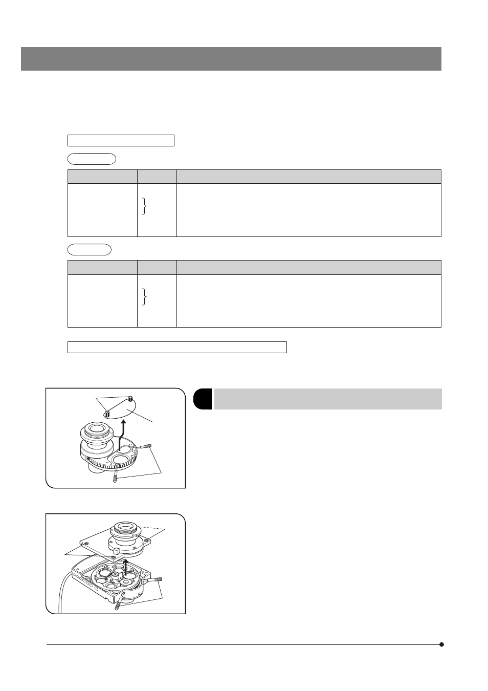
Fig. 36
Fig. 37
2
}For the U-UCD8, refer to the separate instruction manual.
}Do not engage any optical element in the BF (brightfield) light path.
1. Place the condenser in the orientation as shown in Fig. 36, loosen the
detaching screws 1 and remove the cover 2.
With the IX2-LWUCDA2 motorized condenser, remove the four clamping
screws 3 using the Allen screwdriver and remove the top cover. (Fig. 37)
2. Rotate the turret so that the number of the next optical element to be
inserted in the uncovered position is visible. (When the IX2-LWUCDA2 is
used, turret rotation is motorized.)
3. Loosen the optical element position centering screws using the optical
element centering knobs 4. (Figs. 36 & 37)
1
2
4
3
3
4
Attaching the Phase Contrast
Optical Elements
(Figs. 36 to 40)