Irig-b simplified schematic – RuggedCom RUGGEDSWITCH RSG2288 User Manual
Page 29
3. Installation
RuggedCom® RuggedSwitch®
29
RSG2288 Installation Guide Rev 108
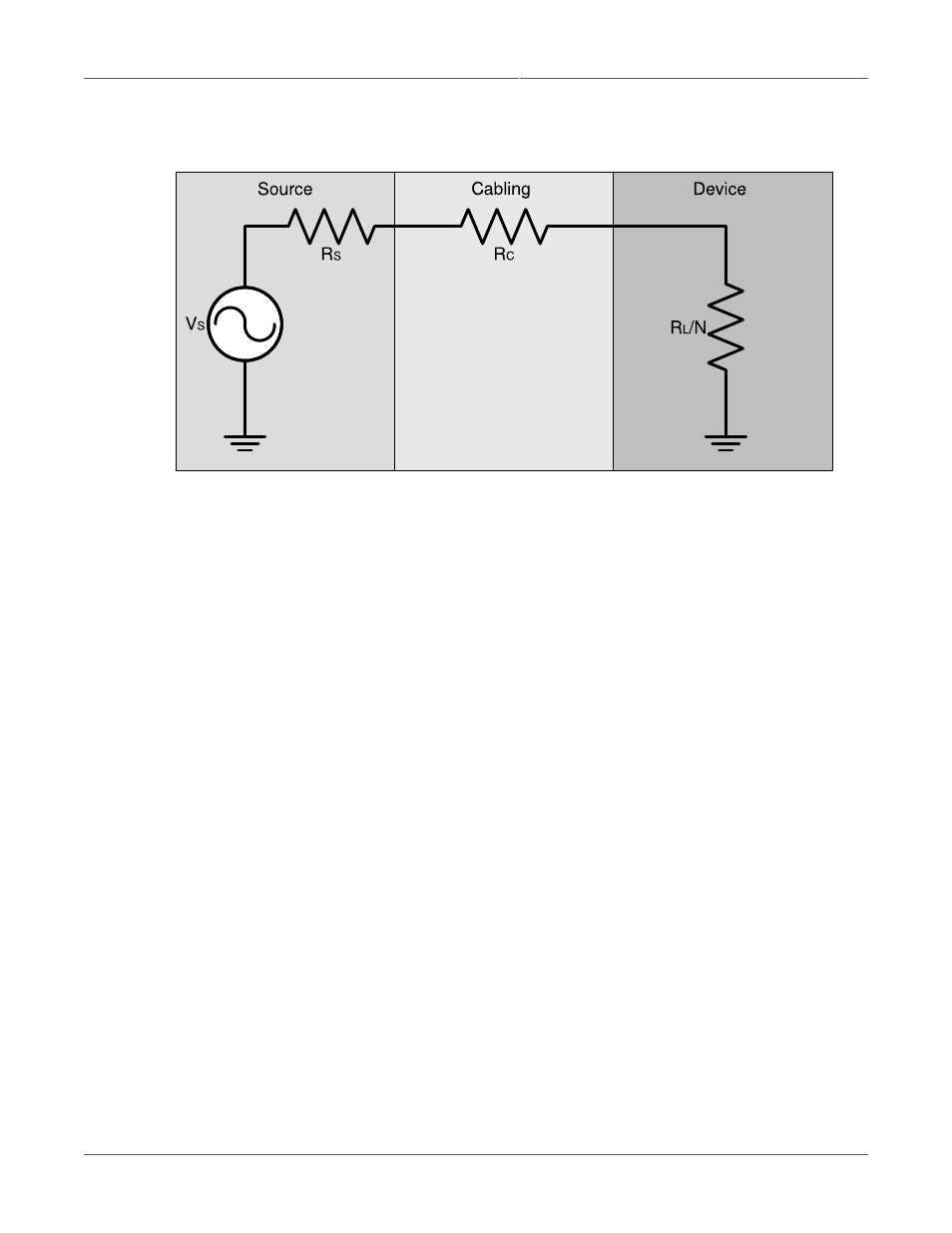
shows a simplified circuit diagram of the interface between an IRIG-B
source and connected devices.
Figure 3.30. IRIG-B Simplified Schematic
The maximum number of devices (N) that can be connected to the source is determined by
checking if the source current (IS) required to drive the connected devices is less than the
maximum drive current the source can provide, and verifying that the load voltage (VL) the
connected devices see is greater than the minimum required voltage. For IRIG-B output port
specifications, see
Section 4.7.2, “IRIG-B Output”
.