Gps antenna cabling, Lightning considerations, Line amplification and filtering – RuggedCom RUGGEDSWITCH RSG2288 User Manual
Page 28: Irig-b outputs, 28 3.3.5. lightning considerations, 28 3.3.6. line amplification and filtering, 28 3.3.7. irig-b outputs, Coaxial cable delay
3. Installation
RuggedCom® RuggedSwitch®
28
RSG2288 Installation Guide Rev 108
3.3.4. GPS Antenna Cabling
Cable Impedance
RuggedCom recommends low loss 50
Ω
coaxial cabling.
Cable Delay
Using any length of coaxial cable will add some time delay to the GPS signal, which degrades the
accuracy of the calculated time and position. The time delay is dependent on the type of dielectric
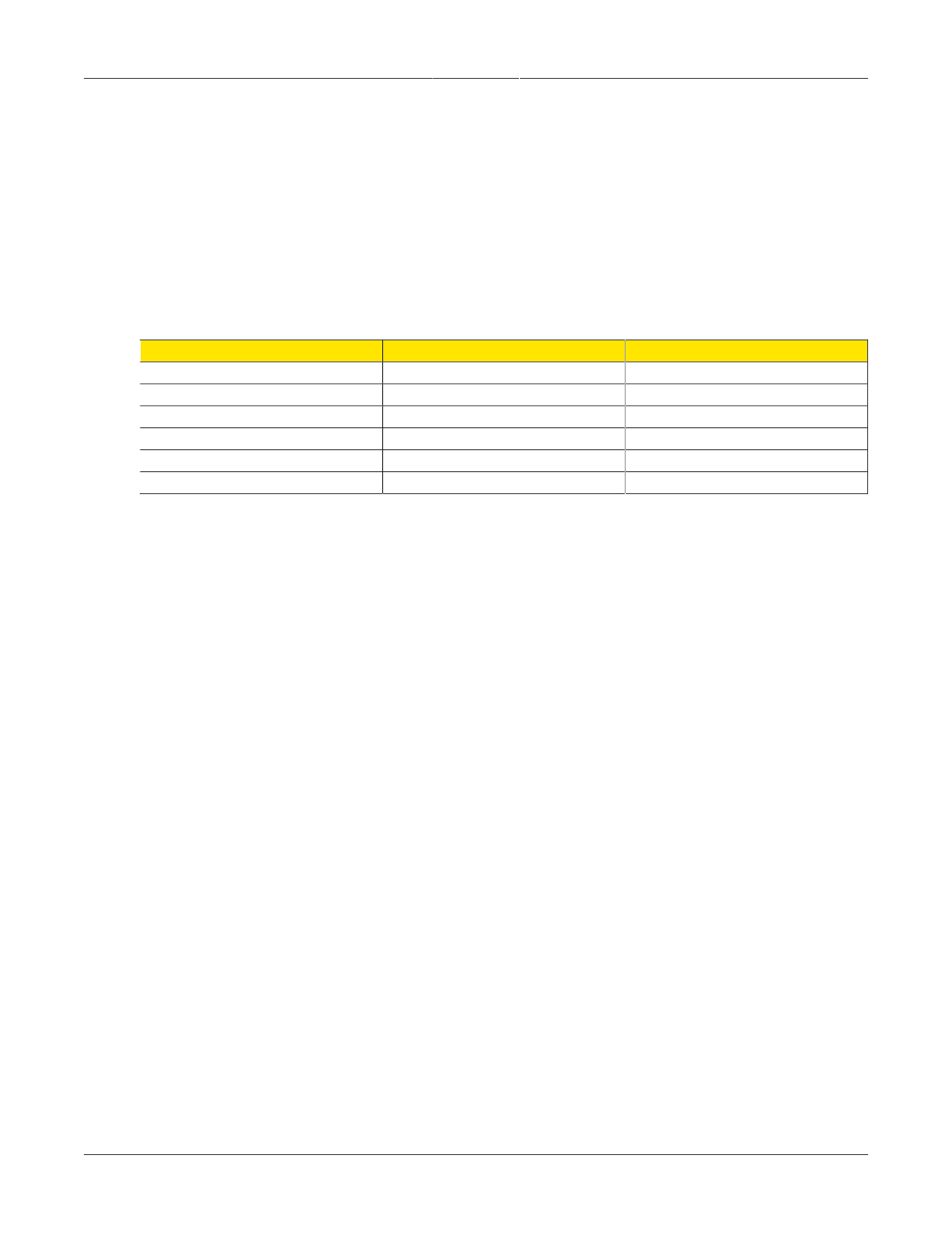
material in the cable and ranges from 1 to 2 ns/ft. The table below gives some examples of the
delay that can be expected based on the dielectric type.
Dielectric Type
Time Delay (ns/ft)
Propagation Velocity (% of c)
Solid Polyethylene (PE)
1.54
65.9
Foam Polyethylene (FE)
1.27
80.0
Foam Polystyrene (FS)
1.12
91.0
Air Space Polyethylene (ASP)
1.15-1.21
84-88
Solid Teflon (ST)
1.46
69.4
Air Space Teflon (AST)
1.13-1.20
85-90
Table 3.10. Coaxial Cable Delay
3.3.5. Lightning Considerations
Although it is not possible to protect the antenna from a direct lighting strike, the antenna and
connected components can be protected from secondary effects through installation location and
protection devices.
Install the antenna at least 15 meters away from and lower than any structures that attract lightning.
GPS antenna damage is usually not the result of a direct lightning strike, but due to high currents
induced by the effects of a lightning strike on a nearby structure. RuggedCom also recommends
installing lightning arrestors in the antenna line to protect the receiver and connected devices. If
a lightning arrestor is installed, it is important to ensure that it has a low impedance path to the
ground.
3.3.6. Line Amplification and Filtering
Although an active antenna has gain, depending on the length of the coaxial cable used, it may
not be enough, in which case a line amplifier will be required as well.
Most active antennas include filters; however, if there is a high potential for electromagnetic
interference, such as from the near field of a radio transmitter, though the antenna system,
additional antenna line filtering may be necessary.
3.3.7. IRIG-B Outputs
The PTP card provides IRIG-B outputs in both AM (Amplitude Modulated) and PWM (Pulse Width
Modulated) formats. The IRIG-B126/B127 signal format is supported on the AM OUT port, and
the IRIG-B006/B007 signal format is supported on the TTL OUT port. Enabling and disabling the
outputs, and selecting between PWM and PPS on the TTL OUT port, is done through software.
The number of IRIG-B devices that can be connected to the AM or PWM sources is dependent
on the cabling type and length as well as the input impedances of the devices.