Transient suppression, Rj45 port pin configuration, Rj45 ethernet pin assignment – RuggedCom RUGGEDSWITCH RSG2288 User Manual
Page 23
3. Installation
RuggedCom® RuggedSwitch®
23
RSG2288 Installation Guide Rev 108
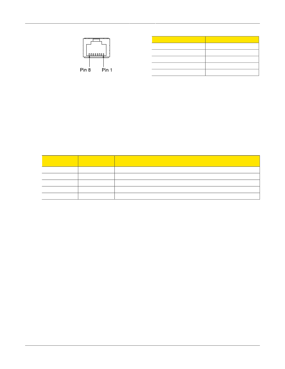
Figure 3.24. RJ45 Port Pin Configuration
Pin
Description
1
RX +
2
RX -
3
TX +
6
TX -
4, 5, 7, 9
No Connection
Table 3.3. RJ45 Ethernet Pin Assignment
3.2.7.2. Gigabit Ethernet 1000Base-TX Cabling Recommendations
The IEEE 802.3ab Gigabit Ethernet standard defines 1000 Mbit/s Ethernet communications over
distances of up to 100 meters using all 4 pairs in category 5 (or higher) balanced unshielded
twisted-pair cabling. For wiring guidelines, system designers and integrators should refer to the
Telecommunications Industry Association (TIA) TIA/EIA-568-A wiring standard that characterizes
minimum cabling performance specifications required for proper Gigabit Ethernet operation. To
ensure reliable, error-free data communication, new and pre-existing communication paths should
be verified for TIA/EIA-568-A compliance.
Table 3.4, “Cabling Categories And 1000Base-TX
summarizes the relevant cabling standards.
Cabling Category
1000Base-
TX Compliant
Required Action
< 5
No
New wiring infrastructure required.
5
Yes
Verify TIA/EIA-568-A compliance.
5e
Yes
No action required. New installations should be designed with Category 5e or higher.
6
Yes
No action required.
> 6
Yes
Connector and wiring standards to be determined.
Table 3.4. Cabling Categories And 1000Base-TX Compliance
Follow these recommendations for copper data cabling in high electrical noise environments:
• Data cable lengths should be as short as possible - ideally limited to 3m (10') in length. Copper
data cables should not be used for inter-building communications.
• Power and data cables should not be run in parallel for long distances, and should be installed
in separate conduits. Power and data cables should intersect at 90° angles when necessary
to reduce inductive coupling.
• Shielded/screened cabling can optionally be used. The cable shield should be grounded at one
single point to avoid the generation of ground loops.
3.2.7.3. Transient Suppression
RuggedCom does not recommend the use of copper cabling of any length for critical real-
time substation automation applications. However, transient suppression circuitry is present
on all copper ports to protect against damage from electrical transients and to ensure IEC
61850-3 and IEEE 1613 Class 1 conformance. This means that during the transient event,
communications errors or interruptions may occur but recovery is automatic. RuggedCom also
does not recommend using these ports to interface to field devices across distances which could
produce high levels of ground potential rise, (i.e. greater than 2500V) during line to ground fault
conditions.