Ruggedswitch® modules, Ethernet panel description, Rsg2288 ethernet port layout – RuggedCom RUGGEDSWITCH RSG2288 User Manual
Page 11: 11 2.2. ethernet panel leds
2. RuggedSwitch® Modules
RuggedCom® RuggedSwitch®
11
RSG2288 Installation Guide Rev 108
2. RuggedSwitch® Modules
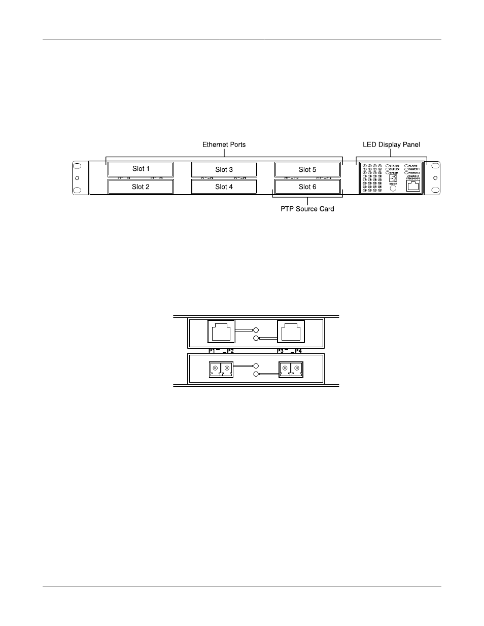
2.1. Ethernet Panel Description
The Ethernet connector panel of the RSG2288 is organized into six slots, five of which are modular
and may be selected at the time the unit is ordered. The figure below shows the physical layout
of these ports.
Figure 2.1. RSG2288 Ethernet Port Layout
Slots 1, 2, 3 and 4 support two-port Ethernet modules up to 1Gbps. Slot 5 supports a one-port
module up to 1Gbps. Slot 6 contains the PTP Source Card (see
Protocol (PTP) Card and IEEE1588 v2”
for details) to support advanced time synchronization.
Each Ethernet module is equipped with an LED per port that indicates link/activity status
information. The LED is solid for ports with a valid link, and blinks for activity.
shows a copper port module in slot 1 and a fiber module in slot 2, along with the
link and activity LEDs for each port.
Figure 2.2. Ethernet Panel LEDs