Ptp card panel description, Ptp card connectors, 26 3.8. ptp card led functions – RuggedCom RUGGEDSWITCH RSG2288 User Manual
Page 26
3. Installation
RuggedCom® RuggedSwitch®
26
RSG2288 Installation Guide Rev 108
NTP (Network Time Protocol) is the standard for synchronizing the clocks of computer systems
throughout the Internet and is suitable for systems that require accuracies in the order of 1 ms.
IRIG-B (Inter Range Instrumentation Group, mod B) time synchronization is an even older,
established, inter-device time synchronization mechanism providing accuracy on the order of 1ms
to 1µs.
The Global Positioning System (GPS), as a source of accurate time, requires an external GPS
antenna input to provide accurate time signals on the order of 500ns. The RSG2288 can use the
GPS receiver on the PTP card to provide the time base for the system.
IEEE 1588 is designed to fill a niche not well served by either of the two older, dominant protocols,
NTP and IRIG-B. IEEE 1588 is designed for local systems requiring accuracies on the order of
100 nanoseconds. IEEE 1588 is also designed for applications that cannot bear the cost of a
GPS receiver at each node or for which GPS signals are inaccessible. Every Ethernet port on the
RSG2288 supports IEEE1588.
The PTP card option is an ideal product for use in existing installations already well served by NTP,
IRIG-B or GPS. It also provides a migration path for the use of the new IEEE 1588 v2 standard.
As more end devices enter the market with IEEE 1588 compatibility this card provides an easy
transition to this new time synchronization standard.
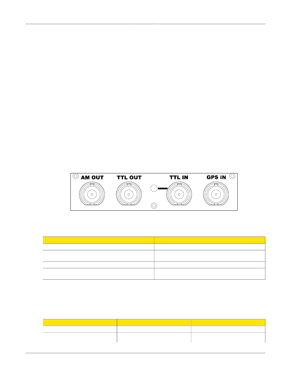
3.3.1. PTP Card Panel Description
Figure 3.29. PTP Card Panel Description
The four BNC connectors on the front panel of the PTP card are defined in the table below:
Connector
Function
AM OUT
IRIG-B126/B127 AM signal output, software enabled
TTL OUT
IRIG-B006/B007 PWM or 1 PPS
signal output, software selectable
TTL IN
TTL-level IRIG-B PWM signal input
GPS IN
Table 3.7. PTP Card Connectors
Note that only one input is active at a time. The IRIG-B PWM input or the GPS input is selected
in software. The color of the LED on the front panel of the PTP card indicates the status of the
incoming timing signal, depending on the input selected:
Color
GPS Input
IRIG-B PWM Input
Green
Lock
Valid signal
Red
Holdover mode (GPS lock has
been achieved but the receiver
Problems with IRIG-B signal