Panel and din rail mounting, Rack mount adapter mounting locations – RuggedCom RUGGEDSWITCH RSG2288 User Manual
Page 13
3. Installation
RuggedCom® RuggedSwitch®
13
RSG2288 Installation Guide Rev 108
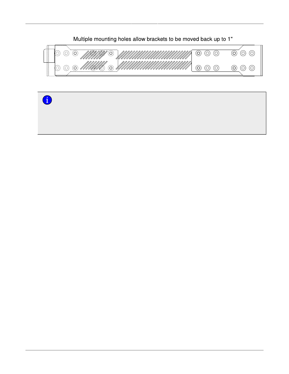
Figure 3.3. Rack Mount Adapter Mounting Locations
Since heat within the RSG2288 is channeled to the enclosure, it is recommended that
1 rack-unit of space (1.75") be kept unpopulated and free of equipment above each
RS2000 series product to allow for a small amount of convectional airflow. Although
forced airflow is not necessary, any increase in airflow will result in a reduction
of ambient temperature that will improve the long-term reliability of all equipment
mounted within the rack space.
3.1.2. Panel and DIN Rail Mounting
RS2000 series products can be ordered as panel/DIN mount chassis. Both options involve the
use of the panel/DIN adapters to be mounted on each side of the chassis enclosure. The adapter
allows for the chassis to be mounted on a standard 1" DIN rail using the grooves in the adapter,
and secured using the included Phillips screw. See
Figure 3.4, “Panel / DIN Rail Mounting Diagram
Figure 3.5, “Panel / DIN Rail Mounting Diagram (Connectors at Bottom)”
for a panel and DIN mounting diagrams.