Setting the i/o chassis addressing node switches – Rockwell SoniCrafter DEVICENET 1771-SDN User Manual
Page 46
Publication 1771-6.5.132 - June 2000
3-8 Hardware Setup
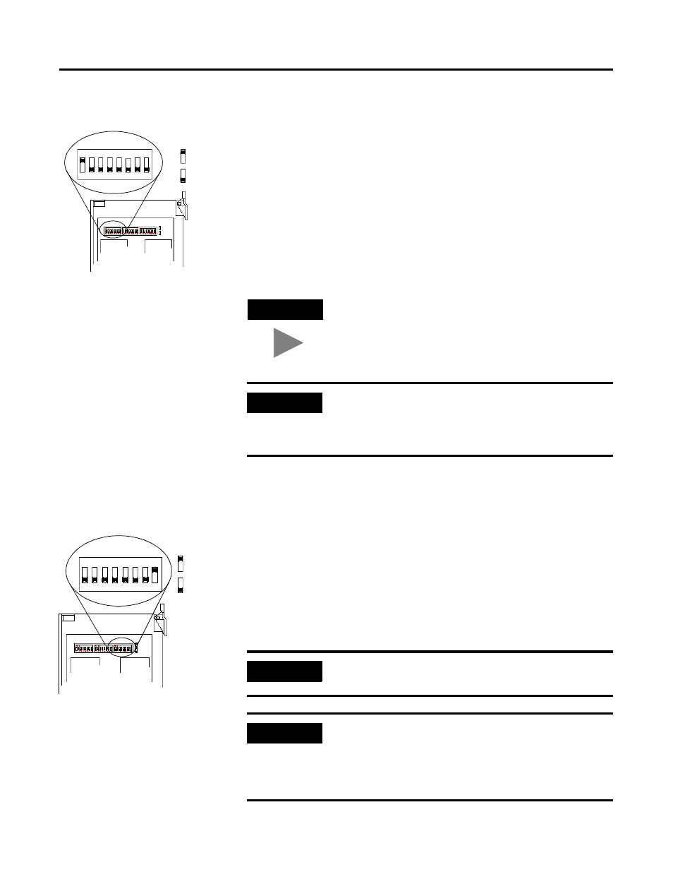
Setting the Channel 1 Data Rate and Node Address Switches
1. Locate the switchbank labeled “Channel 1” on the left side of the
module.
2. Set the DeviceNet Data Rate for Channel 1 to 500K baud for the
example application by setting switch 1 to an ON (“1”) position
and switch 2 to an OFF (“0”) position.
3. Set the DeviceNet node address for Channel 1 to node 0 for the
example application by setting switches 3 through 8 to the OFF
(“0”) position.
Setting the I/O Chassis Addressing Node Switches
Set the I/O chassis addressing mode to 1-slot for the example
application.
1. Locate the switchbank labeled “Configuration” on the left side of
the module.
2. Set switch 7 to an OFF (“0”) position and switch 8 to an ON (“1”)
position.
TIP
Refer to the table on the left side of the module to
set the channel to a different node address. The
address range is 0 to 63.
IMPORTANT
The node address setting must not conflict with the
node address of any other device on the network.
Note that channel 2 is not used for the example
application.
IMPORTANT
Make sure switches 1 through 6 in the Configuration
switchbank always remain in the OFF (“0”) position.
IMPORTANT
The chassis addressing mode setting for the 1771 I/O
chassis (page 3-2) must match the I/O chassis
address setting of the scanner. If the switches do not
match, data will be lost in the data transfer between
the PLC-5 processor and the scanner module.
Channel 1
= ON = 1
= OFF = 0
1
2
3
4
5
6
7
8
O N
= ON = 1
= OFF = 0
Configuration
1
2
3
4
5
6
7
8
O N