Example output mapping scheme, Example characteristics, Example framework – Rockwell SoniCrafter DEVICENET 1771-SDN User Manual
Page 128
Publication 1771-6.5.132 - June 2000
D-6 Data Map Example
Example Output
Mapping Scheme
This example’s output mapping scheme is a simplified and fixed map
of the discrete outputs and data from the device output data table to
DeviceNet devices.
Devices present in the default database are strobed only; therefore,
the output data map bits are mapped into each network’s strobe
message. If the discrete table is available, it serves as a source for the
strobe bits; otherwise, the source is found in block transfer locations.
Example Characteristics
•
strobe is used to send output to the DeviceNet devices
•
poll is disabled
•
DeviceNet A and B ports are connected to separate networks
•
one output data bit each is sent to nodes 1-62 on channel A
•
the output data bits are embedded in the 8 byte (64 bit) data
portion of the DeviceNet strobe message
•
the output bit string source within the strobe message is divided
across the discrete outputs (if any) assigned to the scanner and
the device output data table
Example Framework
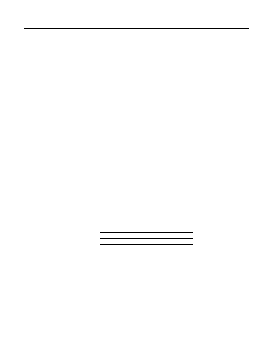
Based on the backplane addressing mode and the scanner’s block
transfer support, the following number of discrete outputs are
supported:
This example adheres to the following structure:
•
when a 1771-SDN scanner is running this configuration, there
cannot be any other 1771-SDN scanner on that network
•
DeviceNet devices may reside only at nodes 1-62
•
address 0 must be used for the scanner
•
the first word in the device output data table contains the
module command word (this is applicable under any mapping
scheme)
•
output bits intended for nodes 1-62 on channel A are mapped to
both the discrete outputs and the device output data table
•
no discrete outputs are used for channel B
Addressing Mode
Discrete Outputs
2-slot
0
1-slot
8
1/2-slot
24