Raypak MVB 5042004 User Manual
Page 44
44
with the blower suction within the tolerances spec-
ified in Table T, contact the factory. The reference
amp draw reading may help to indicate if there is
a problem with the system or if blower adjustment
is required.
Manifold Check
1. Check manifold gas pressure at the gas valve out-
let pressure tap (connection “D” in Fig. 48). This
pressure should read per the values in Table X for
natural and propane gas.
2. If the pressure reading differs by more than ± 0.2
in. WC, STOP – Call the factory for directions
on what to do next!
Safety Inspection
1. Check all thermostats and high limit settings.
2. During the following safety checks leave manome-
ters hooked up, check and record.
3. If other gas-fired appliances in the room are on the
same gas main, check all pressures on the MVB
with all other equipment running.
4. Check thermostats for ON-OFF operation.
5. Check high limits for ON-OFF operation.
6. While in operation, check flow switch operation.
7. Check the low gas pressure switch (if provided).
(For proper adjustment, use the attached
manometers, if available, to set pressure. The
scales on the switch are approximate only.) Low
gas pressure switch (if provided) must be set at
3.0 in. WC for natural gas and propane gas.
8. Make sure that the high gas pressure switch (op-
tional) is set to 3.0 in. WC for both natural gas and
propane gas.
Follow-Up
Safety checks must be recorded as performed.
Turn heater on. After main burner ignition:
1. Check manometer for proper readings.
2. Cycle heater several times and re-check readings.
3. Remove all manometers and replace caps and
screws.
4. Check for gas leaks one more time.
Finishing
1. Record all data on the “Start-up Checklist” located
at the back of this manual.
2. Disconnect the manometers and reconnect the
cap on the fan pressure switch tee and reinsert the
sealing screws into the bleedle valves.
3. Start-up is complete and the heater should be
operating properly.
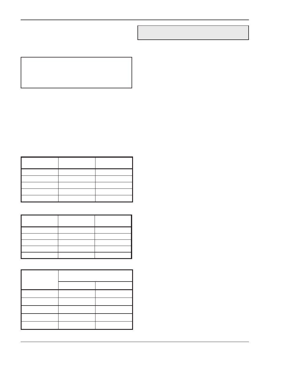
Model No.
Air Pressure
Setting (in. WC)
Setting
Tolerance
504
-2.3
± 0.2 in. WC
754
-2.9
± 0.2 in. WC
1104
-4.0
± 0.2 in. WC
1504
-4.0
± 0.2 in. WC
2004
-4.1
± 0.2 in. WC
Table V: MVB Air Pressure Settings
Model No.
Amp Draw
Setting
Tolerance
504
1.9
+0.0/-0.2
754
2.9
+0.0/-0.2
1104
5.5
+0.0/-0.2
1504
8.1
+0.0/-0.2
2004
13.0
+0.0/-0.5
Table W: MVB Amp Draw (Reference Only)
Model No.
Manifold Gas Pressure Setting
High Fire Values (in. WC)
Natural Gas
Propane Gas
504
-0.1
-0.1
754
-0.4
-0.1
1104
-1.0
-0.2
1504
-2.4
-0.6
2004
-1.0
-0.5
Table X: MVB Manifold Pressure Settings
NOTE: Most commercially available amp probes
are not accurate enough and/or are not shielded well
enough to read accurately in the heater
environment. Blower amp draw readings are for
reference only.
CAUTION: Special manifold and air settings may
be required.