Network Technologies SM-nXm-C5AV-LCD User Manual
Page 22
NTI VEEMUX AUDIO/VIDEO MATRIX SWITCH VIA CAT5
18
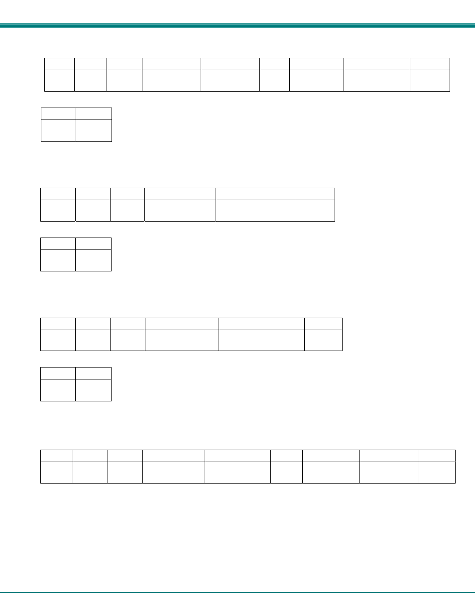
CS- Connect Output Port to Input Port
Command:
Byte 1 Byte 2
Byte 3
Byte 4
Byte 5
Byte 6
Byte 7
Byte 8
Byte 9
‘C’
(0x43)
‘S’
(0x53)
Space
(0x20)
Output
–
1st digit
(0x30
…
0x32)
Output
–
2nd digit
(0x30
…
0x39)
‘,’
(0x2C)
Input
–
1st digit
(0x30
…
0x32)
Input
–
2nd digit
(0x30
…
0x39)
(0x0D)
Response:
Byte 1
Byte 2
‘
∗’
(0x2A)
(0x0D)
This command connects the specified input port to the specified output port.
CA- Connect All Output Ports to Input Port
Command:
Byte 1
Byte 2
Byte 3
Byte 4
Byte 5
Byte 6
‘C’
(0x43)
‘A’
(0x41)
Space
(0x20)
Input
–
1st digit
(0x30
…
0x32)
Input - 2nd digit
(0x30
…
0x39)
(0x0D)
Response:
Byte 1
Byte 2
‘
∗’
(0x2A)
(0x0D)
This command connects all output ports to the specified input port.
SS_01- Enable Auto Status Mode
Command:
Byte 1
Byte 2
Byte 3
Byte 4
Byte 5
Byte 6
‘S’
(0x53)
‘S’
(0x53)
Space
(0x20)
‘0’
(0x30)
‘1’
(0x31)
(0x0D)
Response:
Byte 1
Byte 2
‘
∗’
(0x2A)
(0x0D)
Auto status mode is disabled by default whenever the connection is established, and this command must be entered to enable it.
When auto status mode is enabled, a message will be sent whenever an input/output connection changes from any source. The
format of this message is given in the table below. The first two numeric digits are the output port number and the two after the
colon are the number of the input port that is now connected to it.
Byte 1
Byte 2
Byte 3
Byte 4
Byte 5
Byte 6
Byte 7
Byte 8
Byte 9
‘p’
(0x70)
‘c’
(0x63)
Space
(0x20)
Output
–
1st digit
(0x30
…
0x32)
Output
–
2nd digit
(0x30
…
0x39)
‘:’
(0x3A)
Input
–
1st digit
(0x30
…
0x32)
Input
–
2nd digit
(0x30
…
0x39)
(0x0D)