Rtsi/pxi trigger lines, Rtsi/pxi trigger lines -14, Figure 2-14 – National Instruments PXI NI 5401 User Manual
Page 37: Figure 2-15
Chapter 2
Function Generator Operation
2-14
www.natinst.com
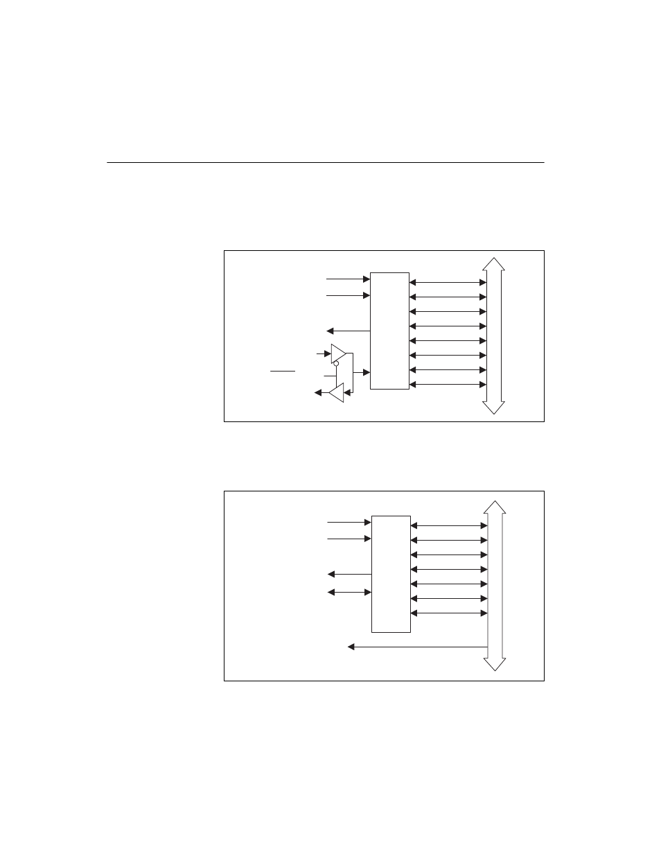
RTSI/PXI Trigger Lines
The NI 5401 for PCI contains seven trigger lines and one RTSI clock line
available over the RTSI bus to send and receive NI 5401-specific
information to other boards that have RTSI connectors. Figure 2-14 shows
the RTSI trigger lines and routing of NI 5401 for PCI signals to the RTSI
switch.
Figure 2-14. RTSI Trigger Lines and Routing for the NI 5401 for PCI
Figure 2-15 shows the PXI trigger lines and routing of NI 5401 for PXI
signals to the RTSI switch.
Figure 2-15. PXI Trigger Lines, 10 MHz Backplane Oscillator, and Routing for the
NI 5401 for PXI
RTSI
Switch
RTSI Bus
RTSI 0
RTSI 1
RTSI 2
RTSI 3
RTSI 4
RTSI 5
RTSI 6
RTSI Osc
Start Trigger
SYNC
RTSI Trigger
Board Clock
RTSI Clock
Master/Slave
RTSI
Switch
PXI Bus
TRIG 0
TRIG 1
TRIG 2
TRIG 3
TRIG 4
TRIG 5
PXI STAR
PXI 10MHz Osc
Start Trigger
SYNC
RTSI Trigger
BOARD_SYNC
- Instrument Driver NI-DMM (12 pages)
- 24-Bit Half/Full-Bridge Analog Input Module NI 9237 (36 pages)
- NI PXIe-8105 (76 pages)
- Fieldpoint CFP-2210 (38 pages)
- NI 781xR (48 pages)
- NI 6233 (180 pages)
- 6508 PCI-DIO-96 (93 pages)
- PXI/CompactPCI Embedded Computer NI PXI-8108 (83 pages)
- NI 9233 (34 pages)
- NI USB-9219 (25 pages)
- GPIB-PC (262 pages)
- cFP-RTD-122 (15 pages)
- USB device 625x (23 pages)
- Isolated Analog Input Modules SCC-AI01 (18 pages)
- NI PCI-6111 (118 pages)
- NI USB-6008 (32 pages)
- PC-DIO-24 (75 pages)
- NI 9474 (31 pages)
- NI 6013 (109 pages)
- PXI-1428 (46 pages)
- NI PCI-5911 (51 pages)
- 2 SD Card Memory Module NI 9802 (16 pages)
- cFP-20xx (24 pages)
- NI USB-9234 (23 pages)
- NI 9871 (24 pages)
- Interface Device NI PCI-1426 (35 pages)
- AT E Series (184 pages)
- 9211A (19 pages)
- Module NI PXI-8250 (39 pages)
- 8330 Series (30 pages)
- NI PXIe-8360 (40 pages)
- Deterministic Ethernet Expansion Chassis NI 9144 (65 pages)
- NI 6509 (23 pages)
- NI MATRIXx Xmath (127 pages)
- NI 9481 (23 pages)
- Monochrome Image Acquisition Device NI 1410 (34 pages)
- VXI-1394 (74 pages)
- NI PXI-8104 (69 pages)
- NI 9235 (38 pages)
- 370620B-01 (17 pages)
- FP-RTD-124 (15 pages)
- VXI-USB (61 pages)
- NI PCI-8254R (45 pages)
- Interface Device NI PCI-8254R (16 pages)