Continuous trigger mode, Figure 2-5. single trigger mode, Figure 2-6. continuous trigger mode – National Instruments PXI NI 5401 User Manual
Page 29: Continuous trigger mode -6, Figure 2-5, Single trigger mode -6, Figure 2-6
Chapter 2
Function Generator Operation
2-6
www.natinst.com
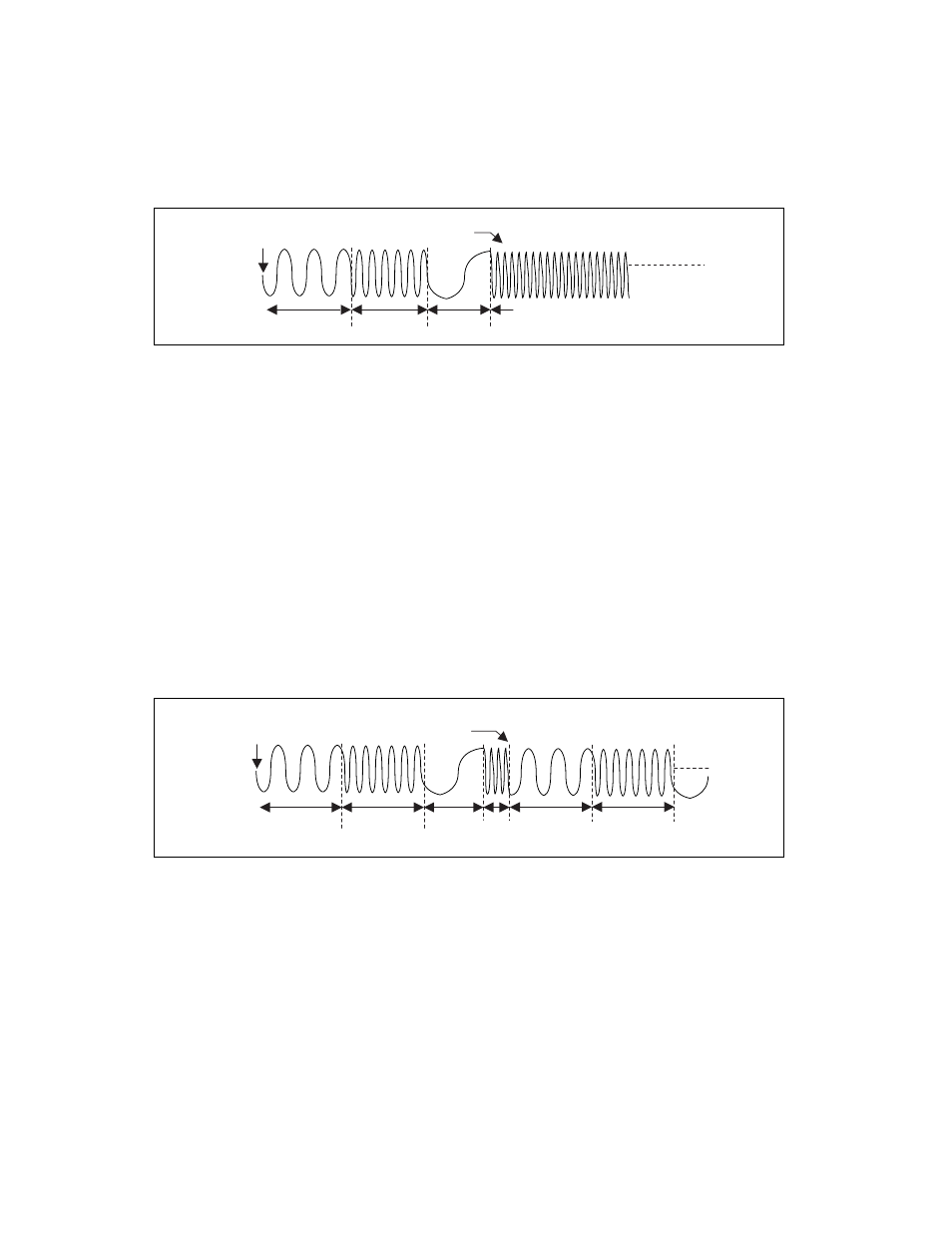
Figure 2-5. Single Trigger Mode
For example, assume that one cycle of a sine wave is stored in the DDS
lookup memory. For stage 1, f1 specifies the sine frequency to be generated
for time
∆
T1, f2 and
∆
T2 for stage 2, and so on. If there are four stages in
the staging list, f4 will be generated continuously until the waveform
generation is stopped.
Continuous Trigger Mode
The waveform you define in the staging list is generated infinitely by
continually cycling through the staging list. After a trigger is received, the
waveform generation starts at the first stage, continues through the last
stage, and loops back to the start of the first stage, continuing until you stop
the waveform generation. Only one trigger is required to start the waveform
generation.
Figure 2-6 illustrates a continuous trigger mode of operation.
Figure 2-6. Continuous Trigger Mode
Start Trigger
Last Stage Generated
Continuously Until Stopped
End of All Stages
f1,
∆
T1
f2,
∆
T2
f3,
∆
T3
f4
Start Trigger
End of All Stages
(f1,
∆
T1
)
(f2,
∆
T2
)
(f3,
∆
T3
)
(f1,
∆
T1
)
(f2,
∆
T2
)
(f4,
∆
T4
)
Repeat
Until Stopped