Stepped trigger mode, Analog output, Figure 2-7. stepped trigger mode – National Instruments PXI NI 5401 User Manual
Page 30: Stepped trigger mode -7, Analog output -7, Figure 2-7
Chapter 2
Function Generator Operation
©
National Instruments Corporation
2-7
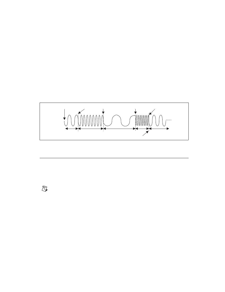
Stepped Trigger Mode
After a start trigger is received, the waveform defined by the first stage is
generated. Then, the device waits for the next trigger signal. On the next
trigger, the waveform described by the second stage is generated, and so on.
Once the staging list is exhausted, the waveform generation returns to the
first stage and continues in a cyclic fashion.
Figure 2-7 illustrates a stepped trigger mode of operation. Switching from
stage to stage is phase continuous. In this mode, the time instruction is not
used. The trigger paces the waveform generation from one frequency to the
other.
Figure 2-7. Stepped Trigger Mode
Analog Output
Analog waveforms are generated as follows:
1. The 12-bit digital waveform data is fed to a high-speed DAC.
2. A lowpass filter filters the DAC output.
3. This filtered signal is amplified before it goes to a 10 dB attenuator.
Note
The DAC output can be fine-tuned for gain and offset. Since the offset is adjusted
before the main attenuators and amplifier, it is referred to as pre-attenuation offset. This
fine-tuning of gain and offset is performed by separate DACs.
4. The output from the 10 dB attenuator then goes to the main amplifier,
which can provide up to ±5 V levels into 50
Ω
. An output relay can
switch between ground level and the main amplifier. Refer to the
section of this document for additional information
about this relay.
5. The output of this relay goes to a series of passive attenuators.
6. The output of the attenuators goes through a selectable output
impedance of 50 or 75
Ω
to the I/O connector.
End of All Stages
f1 f2 f3 f4
Start Trigger Start Trigger Start Trigger
Start Trigger
Start Trigger
f1