Installation, Installation -8, Figure 3-7 – Panasonic CPC-EX User Manual
Page 36: Printed circuit card installation -8
Chapter 3. Cabinet Installation
Section 300-Installation
3-8
DBS Manual - Revised April 2000
DBS-2.3/9.2-300
Installation
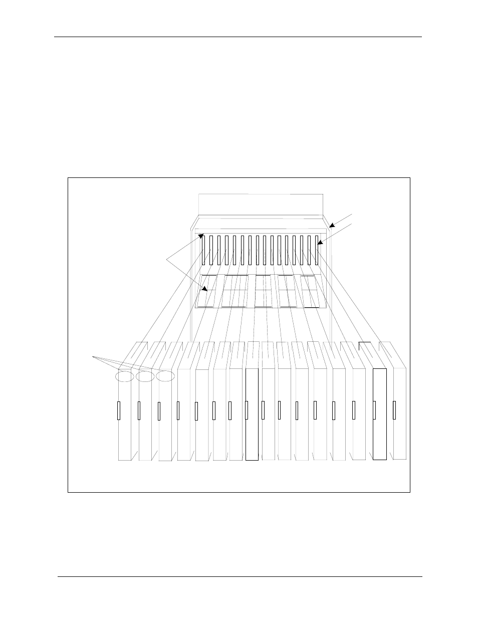
1. With the lettering on the card pointed up, position the card within the slot
2. Hold the card on the top and bottom edges with both hands and carefully
push the card into the slot.
3. When the connector at the far end of the card touches the corresponding
connector on the backplane, press the card in until it is firmly seated.
Figure 3-7. Printed circuit card installation
TRK1 TRK2 TRK3 EC1 EC2 EC3 EC4 EC5 EC6 EC7 EC8 EC/TRK SCC CPC AUX1 AUX2
TRK
TRK
TRK
EC
*
EC
EC
EC
EC
EC
EC
EC
TRK
or
T1
or
EC
SCC
CPC
or
M FR#
M FR
or
API
API
or
CBL
or
M FR
G uide
Slot Label
C onnector
C ard
Label
The M FR card can be installed in the C PC slotofslave cabinets.
*
See also other documents in the category Panasonic Phones:
- kx-t7731 (16 pages)
- kx-dt343 (24 pages)
- KX-TG6052AL (52 pages)
- DBS 576 (18 pages)
- KX-TD816 (131 pages)
- KX-T2375ALW (36 pages)
- KX-FPG378 (110 pages)
- KX-PW616 (24 pages)
- KX-TDA50 (40 pages)
- KX-PW30CL2 (6 pages)
- KX-FM280 (172 pages)
- KX-TDA30 (214 pages)
- KX-T2365A (17 pages)
- KX-T7450 (31 pages)
- VE-GP03 (2 pages)
- KX-TCD535HK (116 pages)
- X-TSC14B (52 pages)
- VA-309 (43 pages)
- KEY TELEPHONE (72 pages)
- BB-GT1500C (108 pages)
- KX-TG2257S (96 pages)
- 44-Series (87 pages)
- KX-TG8220E/KX-TG8222E (10 pages)
- Easa-Phone KX-T2342A (14 pages)
- KX-WP1050E (9 pages)
- KX-T7630E (12 pages)
- KX-TDA30AL (16 pages)
- IP8840 (36 pages)
- BB-GT1540 (112 pages)
- 524X07801B (334 pages)
- KX-TG2356 (87 pages)
- HYBRID IP-PBX KX-TDA50 (158 pages)
- DBS 576HD (4 pages)
- KX-T7700 (2 pages)
- KX-TS550B (2 pages)
- KX-TG5456 (76 pages)
- VA-12020 (4 pages)
- KX-TDA0484 (68 pages)
- KX-TG7622 (100 pages)
- VA-20861 (56 pages)
- KX-T2395D-W (54 pages)
- JOIP BB-GT1540E (112 pages)
- KX-TC1220NZW (60 pages)
- KX-TDA (87 pages)