2 ptz camera connection, Solder side of 15-pin d-sub connector – Planet Technology DVR-460 User Manual
Page 14
3.2.2 PTZ camera connection
1) Power connection:
Connect the PTZ camera with indicated power supply.
2) Video cable connection:
Connect the PTZ camera video output to the DVR video input with a coaxial cable / RCA
line and BNC connector.
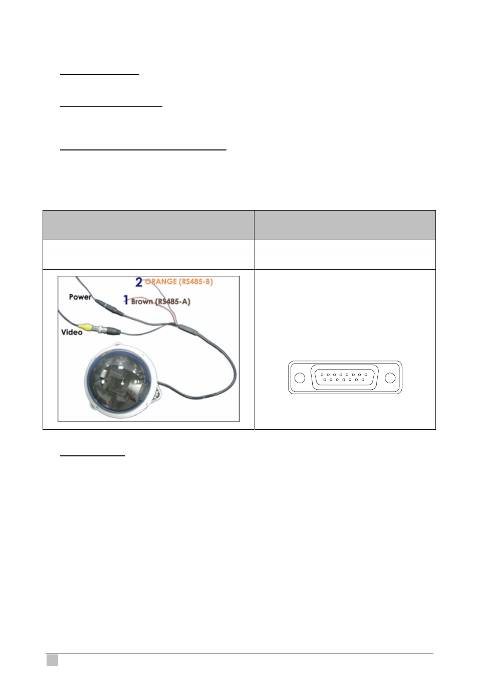
3) RS485-A & RS485-B wires connection:
Solder the RS485-A (brown) and RS485-B (orange) wires of the PTZ camera to the
corresponding pins on the solder side of the 15 PIN D-Sub connector (see the figure
below). To protect the naked wires, use the insulation tape to cover on the twisted wires.
PTZ Camera –
RS485-A and RS485-B wires of the PTZ camera
For 4CH DVR –
15 PIN D-Sub Connector
RS485-A: Brown wire RS485-A:
PIN 11
RS485-B: Orange wire RS485-B:
PIN 10
Solder Side of
15-pin D-Sub connector
RS485-A: PIN11; RS485-B: PIN10
1
9
12
13
14
15
16
17
2
3
4
5
6
7
8
10
11
4) Camera Setup:
For detailed camera title, ID, protocol and baud rate setup, please refer to “7.3
REMOTE”.
DVR-460 User Guide
14