Carrier motor assembly removal, Carrier motor assembly removal -15 – Lexmark 4227-X00 User Manual
Page 78
Repair Information
4-15
4227-X00
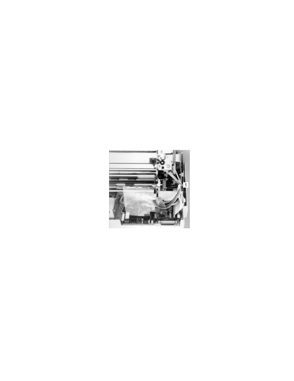
Carrier Motor Assembly Removal
1. Remove the top cover.
See
“Top Cover Removal” on page 4-6
.
2. Disconnect carrier motor connectors CN9 and CN15 from the
main logic board.
3. Loosen the two tension pulley plate screws. Pull upward on both
sides of the belt to move the tension pulley plate as far as
possible toward the center of the printer, then retighten the large
screw.
4. Remove the three screws [1] holding the motor to its bracket.
5. Remove the carrier motor.
Reinstallation:
1. Be sure the motor pulley goes inside the belt as the motor is
being reinstalled.
2. The shaft bearing should be under the ribbon motor plate,
mounted to the carrier motor shaft.
3. Ribbon motor screws should be loosened when reinstalling the
carrier motor.
4. Tighten the carrier motor screws before you tighten the ribbon
motor assembly mounting screws.
- E260d (142 pages)
- 6600 Series (173 pages)
- 10N0227 (1 page)
- Z12 (2 pages)
- 301 (144 pages)
- NO. 35 (1 page)
- Z65n (111 pages)
- dn2 (217 pages)
- 10E (144 pages)
- Z2300 (54 pages)
- 230 (213 pages)
- 310 Series (2 pages)
- PRO700 (24 pages)
- C 720 (18 pages)
- C520 (145 pages)
- X656 MFP (104 pages)
- Prospect Pro207 (27 pages)
- 337 (258 pages)
- OptraImage 242 (207 pages)
- T64x (6 pages)
- C524 (146 pages)
- 4098-001 (70 pages)
- 1200 Series (21 pages)
- X650 Series (8 pages)
- 5300 (179 pages)
- 302 (274 pages)
- 4549 (235 pages)
- 202 (320 pages)
- 4076-0XX (89 pages)
- 10N0016 (1 page)
- 5025 (171 pages)
- 1361760 (1 page)
- C 546dtn (6 pages)
- Interpret S400 (40 pages)
- x6575 (2 pages)
- 27S2156-001 (2 pages)
- MENUS AND MESSAGES C522 (55 pages)
- Z35 (101 pages)
- Z25 (24 pages)
- series x5100 (77 pages)
- Z82 (105 pages)
- 2500 Series (76 pages)
- 1200 (208 pages)
- Z33 (114 pages)
- 7600 Series (181 pages)