5 sda and scl waveform characteristics, C bus controller, C bus interface – Lucent Technologies MN10285K User Manual
Page 300
I
2
C Bus Controller
SDA and SCL Waveform Characteristics
MN102H75K/F75K/85K/F85K LSI User Manual
Panasonic Semiconductor Development Company
299
Panasonic
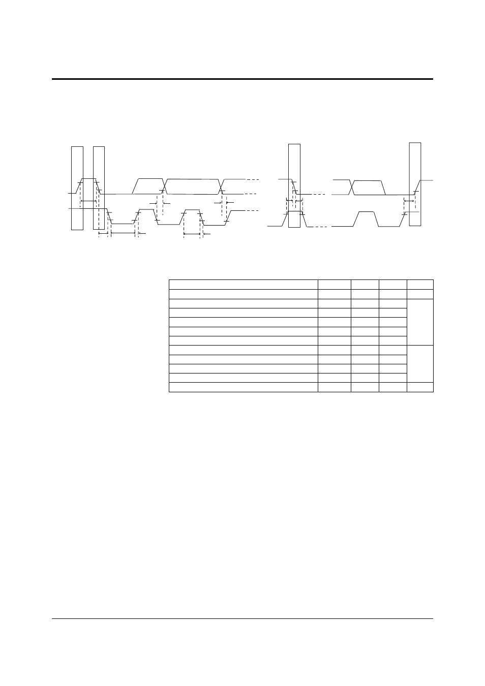
13.5 SDA and SCL Waveform Characteristics
Figure 13-6 and table 13-5 provide the timing definitions and specifications for
the for the MN102H75K/85K I
2
C bus interface.
Figure 13-6 SDA and SCL Waveforms
SDA
t
HD
; DAT
P
SCL
t
HIGH
t
BUF
t
HD
;STA
t
LOW
t
R
t
SU
; STO
t
HD
; STA
t
F
t
SU
; DAT
t
SU
; STA
S
Sr
P
Table 13-5 SDA and SCL Waveform Characteristics
Parameter
Symbol
Min
Max
Unit
SCL clock frequency
f
SCL
0
100
kHz
Bus free time between a stop and start condition
t
BUF
20
—
µs
Hold time (repeated) start condition
t
HD;STA
4.0
—
Low period of the SCL clock
t
LOW
4.7
—
High period of the SCL clock
t
HIGH
4.0
—
Setup time for a repeated start condition
t
SU;STA
4.7
—
Data hold time
t
HD;DAT
300
—
ns
Data setup time
t
SU;DAT
250
—
SDA and SCL rise time
t
R
—
1000
SDA and SCL fall time
t
F
—
300
Stop condition setup time
t
SU;STO
4.0
µs