4 identifying the data format, Ir remote signal receiver – Lucent Technologies MN10285K User Manual
Page 221
IR Remote Signal Receiver
IR Remote Signal Receiver Operation
Panasonic Semiconductor Development Company
MN102H75K/F75K/85K/F85K LSI User Manual
220
Panasonic
8.3.4
Identifying the Data Format
The microcontroller determines the logic levels of the data by testing the interval
between remote signal edges. Table 8-1 shows the intervals that the microcon-
troller interprets as 0 and 1 for both HEAMA and 5-/6-bit formats. Table 8-2
shows the conditions for identifying long and short data.
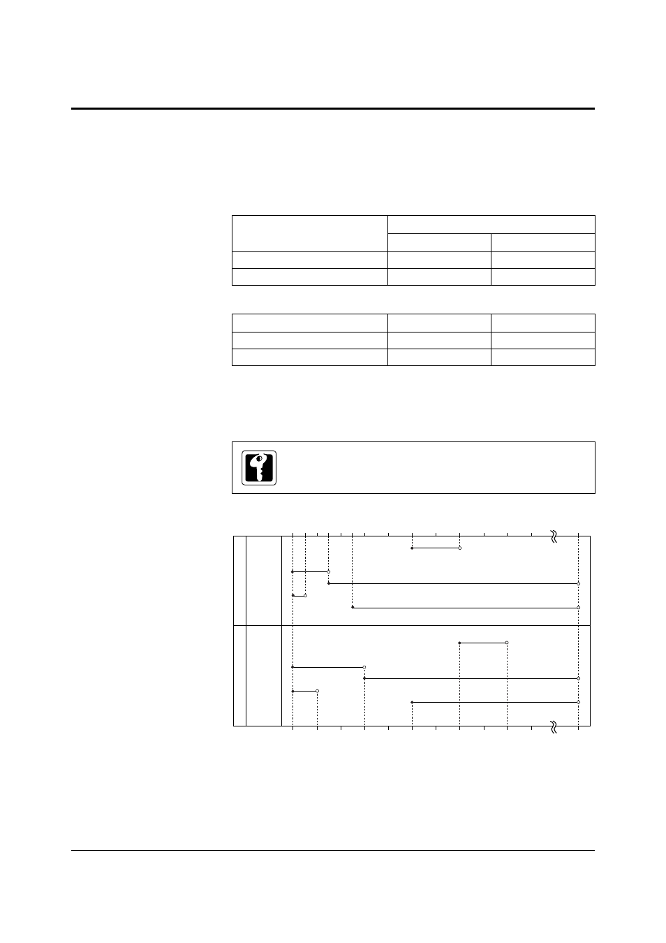
The 6-bit counter regulates data format detection. When the microcontroller detects
a data leader, it sets the LONGDF bit of the clock status register, RMCS, to indicate
long data. Figure 8-5 is a graphic representation of all the conditions for identifying
the data format.
Table 8-1 Logic Level Conditions for Data Formats
Operating Mode
Logic Level Conditions
Data = 0
Data = 1
HEAMA format
< 6 T
S
cycles
≥
6 T
S
cycles
5-/6-bit format
< 12 T
S
cycles
≥
12 T
S
cycles
Table 8-2 Long and Short Data Identification
Operating Mode
Long Data
Short Data
HEAMA format
≥
10 T
S
cycles
< 2 T
S
cycles
5-/6-bit format
≥
20 T
S
cycles
< 4 T
S
cycles
When the microcontroller detects a data trailer, the hardware automatically
shuts off the supply to sampling clock T
S
, which the 6-bit counter counts.
The counter resets and the clock supply restarts at the next edge detection.
Figure 8-5 Conditions for Detecting Data Formats
0
2
4
6
8 10 12
16
20
24
28
32
36
40
64 T
S
0
4
8
12
16
20
24
28
32
36
40
64 T
S
Leader (= 32 T
S
)
Long
Data = 1 (= 16 T
S
)
Data = 0 (= 8 T
S
)
Short
Data = 0 (= 4 T
S
)
Data = 1 (= 8 T
S
)
Short
Long
Leader (= 24 T
S
)
(When RMLD[3:0] = x’6’)
Leader
Data
format
detection
Short/long
detection
Leader
Data
format
detection
Short/long
detection
5-/6-bit format
HEAMA format