I/o ports – Lucent Technologies MN10285K User Manual
Page 279
I/O Ports
I/O Port Control Registers
Panasonic Semiconductor Development Company
MN102H75K/F75K/85K/F85K LSI User Manual
278
Panasonic
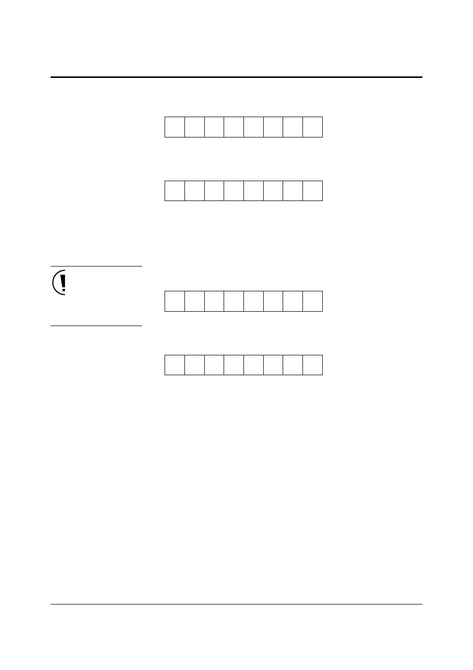
P0IN–P5IN: Ports 0–5 Input Registers
x’00FFD0’–x’00FFD5’
P7IN–P8IN: Ports 7–8 Input Registers
x’00FFD8’–x’00FFDA’
P6IN: Port 6 Input Register
x’00FFD6’
The PnIN registers contain the port input data. The bit number corresponds
to the associated pin number. For instance, P0IN7 applies to the P07 pin.
These are 8-bit access registers.
When using P57 as a port, set
SIFSEL0 (PCNT0 x’FF90’ bp12)
to ’0’.
P0DIR–P5DIR: Ports 0–5 I/O Control Registers
x’00FFE0’–x’00FFE5’
P7DIR–P8DIR: Ports 7–8 I/O Control Registers
x’00FFE8’–x’00FFEA’
P6DIR: Port 6 I/O Control Register
x’00FFE6’
The PnDIR registers control the I/O direction of the ports. The bit number
corresponds to the associated pin number. For instance, P0DIR7 applies to
the P07 pin. These are 8-bit access registers.
0: Input
1: Output
Bit:
7
6
5
4
3
2
1
0
PnIN7
PnIN6
PnIN5
PnIN4
PnIN3
PnIN2
PnIN1
PnIN0
Reset:
Pin
Pin
Pin
Pin
Pin
Pin
Pin
Pin
R/W:
R
R
R
R
R
R
R
R
Bit:
7
6
5
4
3
2
1
0
0
0
0
0
0
0
P6IN1
P6IN0
Reset:
0
0
0
0
0
0
Pin
Pin
R/W:
R
R
R
R
R
R
R
R
Bit:
7
6
5
4
3
2
1
0
PnDIR7 PnDIR6 PnDIR5 PnDIR4 PnDIR3 PnDIR2 PnDIR1 PnDIR0
Reset:
0
0
0
0
0
0
0
0
R/W:
R/W
R/W
R/W
R/W
R/W
R/W
R/W
R/W
Bit:
7
6
5
4
3
2
1
0
0
0
0
0
0
0
P6DIR1 P6DIR0
Reset:
0
0
0
0
0
0
0
0
R/W:
R
R
R
R
R
R
R/W
R/W