Profibus interface center, Spc3 – Siemens SPC3 User Manual
Page 18
PROFIBUS Interface Center
SPC3
Page 16
V1.3
SPC3 Hardware Description
2003/04
Copyright (C) Siemens AG 2003. All rights reserved.
Address
Intel
/Motorola
Name Bit No. Significance
16H
R_TS_Adr
7..0
Set up station address of the relevant SPC3
17H
reserved
Pointer to a RAM address which is presetted with 0FFH
18H
19H
R_User_Wd_Value
7..0
Based on an internal 16-bit wachdog timer, the user is
monitored in the DP_Mode.
19H
18H
R_User_Wd_Value 15
..8
1AH
R_Len_Dout_Puf
Length of the 3 Dout buffers
1BH
R_Dout_buf_Ptr1
Segment base address of Dout buffer 1
1CH
R_Dout_buf_Ptr2
Segment base address of Dout buffer 2
1DH
R_Dout_buf_Ptr3
Segment base address of Dout buffer 3
1EH
R_Len_Din_buf
Length of the 3 Din buffers
1FH
R_Din_buf_Ptr1
Segment base address of Din buffer 1
20H
R_Din_buf_Ptr2
Segment base address of Din buffer 2
21H
R_Din_buf_Ptr3
Segment base address of Din buffer 3
22H
reserved
Preset with 00H.
23H
reserved
Preset with 00H.
24H
R Len Diag buf1
Length of Diag buffer 1
25H
R Len Diag buf2
Length of Diag buffer 2
26H
R_Diag_Puf_Ptr1
Segment base address of Diag buffer 1
27H
R_Diag_Puf_Ptr2
Segment base address of Diag buffer 2
28H
R Len Cntrl Pbuf1
Length of Aux buffer 1 and the control buffer belonging to it,
for example, SSA-Buf, Prm-Buf, Cfg-Buf, Read-Cfg-Buf
29H
R Len Cntrl Puf2
Length of Aux-Buffer 2 and the control buffer belonging to
it, for example, SSA-Buf, Prm-Buf, Cfg-Buf, Read-Cfg-Buf
2AH
R Aux Puf Sel
Bit array, in which the assignments of the Aux-buffers ½ are
defined to the control buffers, SSA-Buf, Prm-Buf, Cfg-Buf
2BH
R_Aux_buf_Ptr1
Segment base address of auxiliary buffer 1
2CH
R_Aux_buf_Ptr2
Segment base address of auxiliary buffer 2
2DH
R_Len_SSA_Data
Length of the input data in the Set_Slave_Address-buffer
2EH
R SSA buf Ptr
Segment base address of the Set_Slave_Address-buffer
2FH
R_Len_Prm_Data
Length of the input data in the Set_Param-buffer
30H
R_Prm_buf_Ptr
Segment base address of the Set_Param-buffer
31H
R_Len_Cfg_Data
Length of the input data in the Check_Config-buffer
32H
R Cfg Buf Ptr
Segment base address of the Check_Config-buffer
33H
R_Len_Read_Cfg_Data
Length of the input data in the Get_Config-buffer
34H
R_Read_Cfg_buf_Ptr
Segment base address of the Get_Config-buffer
35H
reserved
Preset with 00H.
36H
reserved
Preset with 00H
37H
reserved
Preset with 00H.
38H
reserved
Preset with 00H.
39H
R_Real_No_Add_Change
This parameter specifies whether the DP slave address may
again be changed at a later time point.
3AH
R_Ident_Low
The user sets the parameters for the Ident_Low value.
3BH
R_Ident_High
The user sets the parameters for the Ident_High value.
3CH
R_GC_Command
The Global_Control_Command last received
3DH
R_Len_Spec_Prm_buf
If parameters are set for the Spec_Prm_Buffer_Mode (see
mode register 0), this cell defines the length of the param
buffer.
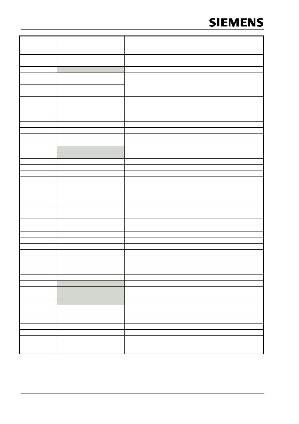
Figure 4.4: Assignment of the Organizational Parameters