Powering on and powering off the server, Powering on and powering off the server” on, Figure 1-2 – Sun Microsystems Sun Fire X2100 M2 User Manual
Page 10: Table 1-1
6
Sun Fire X2100 M2 Server Installation Guide • August 2006
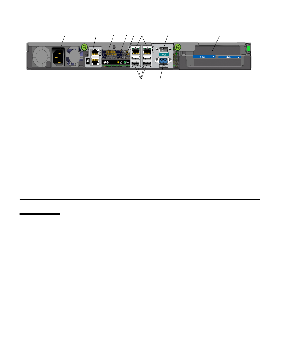
FIGURE 1-2
Back Panel
Powering On and Powering Off the
Server
You only need to apply standby power to the server at this point so that you can
perform initial configuration of the service processor. Procedures for powering on to
main power mode and for shutting down from main power mode are also included in
this section.
TABLE 1-1
Back Panel
Label
Connector/Slot
Label
Connector/Slot
1
Power connector
6
NVIDIA Ethernet connectors (LAN-2 left,
LAN-3 right)
2
Broadcom Ethernet connectors (LAN-0 top,
LAN-1 NET MGT bottom)
7
Serial management/DB9 RS-232 serial port
3
System identification button/LED
8
PCI-Express slots
4
Fault LED
9
Onboard HD15 video connector
5
Power LED
10
USB 2.0 connectors (4)
2
10
9
6
3
4
5
7
8
1