Details – Sharp Digital Laser Copier/Printer AR-5127 User Manual
Page 32
AR-5127 SIMULATION 8 - 4
3. Details
Operation/procedure
Enter the number, set the magnification ratio and the original size and
press the [OK] key, and the scanner unit will operate in a speed corre-
sponding to the setup.
The fixed magnification ratio (25% to 400%) can be changed in 11
steps with [
↑
] [
↓
] keys.
(AB series) 25
→
50
→
70
→
81
→
86
→
100
→
115
→
122
→
141
→
200
→
400
(Inch series) 25
→
50
→
64
→
77
→
95
→
100
→
121
→
129
→
141
→
200
→
400
The scan counter is displayed during execution.
Operation/procedure
The status of sensors and detectors in the scanner section is dis-
played. The active sensors and detectors are highlighted.
Operation/procedure
Set a document on the APF paper feed tray, and fix it with tape.
Enter the number, set the magnification ratio and the original size and
press the [OK] key, and the SPF unit will operate in a speed corre-
sponding to the setup.
51
8
Used to set to disable the operation of the
separation pawl of the photoconductor drum.
9
Used to adjust ON/OFF timing of the separation
voltage.
53
8
Used to adjust the mirror unit SPF scan position
automatically.
For the SPF scan position auto adjustment, the
mirror unit is shifted to 11mm before the SPF glass
cover edge and is moved by self-boost, and
images are scanned in each step, and the position
from the glass cover edge is automatically
detected.
[Adjustment value]
Default: 50
Setting range: 1 to 99
Adjustment unit 1 = about 0.127mm
61
1
Used to test the operation of the LSU.
63
1
Used to check the result of shading correction.
(The shading correction data are displayed.)
7
Used to adjust the SPF white correction start pixel
position automatically.
This adjustment is performed after the lens unit is
replaced.
64
1
Self print
Key input = 1
Self print is performed in the 2-by-4 mode (2-line
print and 4-line non-print).
Key input = 2
Grid print is performed. (1cm, 1-dot width WLT/A3
print (A3 main scan, WLT sub scan))
65
5
Used to check the operation panel.
66
1
FAX related soft SW setting
2
Initial set for the value of the FAX soft SW
3
FAX PWB memory check
4
Signal send mode
6
Printing the confidential password
7
Print the screen memory contents
8
Voice Message send
10
Image data memory clear
11
300bps signals send
13
Send test and adjustment of the dial pulse and
DTMF signal.
17
DTMF signal send
21
FAX information print
*22
Handset sound volume adjustment
30
Recognize TEL/LIU state change.
32
Receive data check
34
Communication time measurement display
37
Speaker sound volume adjustment
38
Time setting/check
41
CI signal check
50
FAST SRAM clear
51
Signal detection check
52
Pseudo-ringer check
53
SRAM backup
67
*11
Used to set the Select-IN signal.
*14
Used to check write/comparison of flash programs.
*17
Used to clear NVRAM.
*18
Used to clear the data area for FLASH ROM
Network Scanner Application.
*20
Used to check the network connection when a
scanner option is installed.
Code
Function
Main
Sub
1
1-1
Purpose
Operation test/check
Function
(Purpose)
Used to check the operation of the scanner unit and its
control circuit.
Section
Optical (Image scanning)
Item
Operation
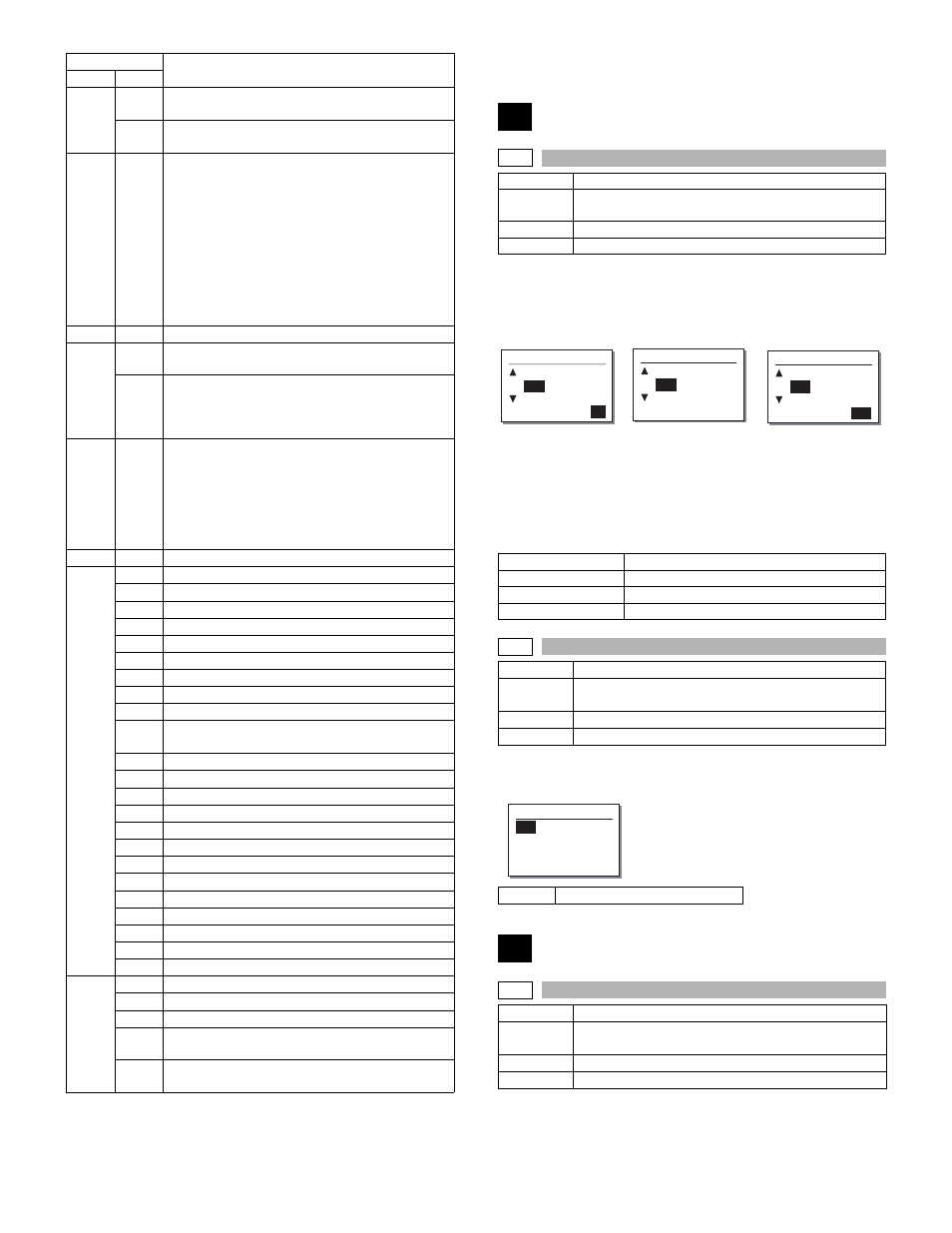
(Initial screen)
(Input/Selection screen) (Executing screen)
Magnification ratio
25% to 400%
Default
100%
Document size
Varies depending on the destination.
Set number of times
1 to 999 (0: Continuous operation)
1-2
Purpose
Operation test/check
Function
(Purpose)
Used to check the operation of sensor and detector in
the scanning (read) section and the related circuit.
Section
Optical (Image scanning)
Item
Operation
MHPS
Mirror home position sensor
2
2-1
Purpose
Operation test/check
Function
(Purpose)
Used to check the operation of the SPF unit and the
related circuit.
Section
SPF
Item
Operation
Sim1-1 SCAN CHECK
115% A3
100%
86%
ZOOM <100%>
0
Sim1-1 SCAN CHECK
115% A3
100%
86%
ZOOM <100%> EXEC
Sim1-1 SCAN CHECK
115% A3
100%
86%
ZOOM <100%>
EXEC
Sim1-2 SENSOR CHECK
MHPS