Sharp Digital Laser Copier/Printer AR-5127 User Manual
Page 24
AR-5127 ADJUSTMENTS 7 - 5
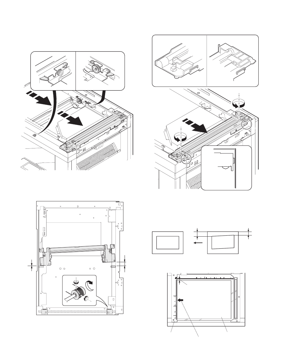
3) Manually turn the mirror base drive pulley and bring No. 2/3 mirror
base unit into contact with the positioning plate.
At that time, if the front frame side and the rear frame side of No. 2/
3 mirror base unit are brought into contact with the positioning
plate at the same time, the mirror base unit parallelism is proper.
If one of them is in contact with the positioning plate, perform the
adjustment of 4).
4) Loosen the set screw of the scanner drive pulley which is not in
contact with No. 2/3 mirror base unit positioning plate.
5) Without moving the scanner drive pulley shaft, manually turn the
scanner drive pulley until the positioning plate is brought into con-
tact with No. 2/3 mirror base unit, then fix the scanner drive pulley.
6) Put No. 2/3 mirror base unit on the positioning plate again, push
the projections on the front frame side and the rear frame side of
the copy lamp unit to the corner frame, and tighten the wire fixing
screw.
(8) Sub scanning direction (scanning direction) distortion
adjustment (Winding pulley position adjustment)
This adjustment must be performed in the following cases:
• When the mirror base drive wire is replaced.
• When the lamp unit, or No. 2/3 mirror holder is replaced.
• When a copy as shown is made.
1) Set A3 (11" x 17") white paper on the original table as shown
below.
Lb
La
Original
Copy
Paper exit
direction
Place a little clearance from
the rear side original guide.
Glass holding plate
Fit the paper edge and
the glass holding plate edge.
A3 (11" x 17") white paper