Sharp Digital Laser Copier/Printer AR-5127 User Manual
Page 22
AR-5127 ADJUSTMENTS 7 - 3
Setup of various copy conditions: Similar to the normal copy mode.
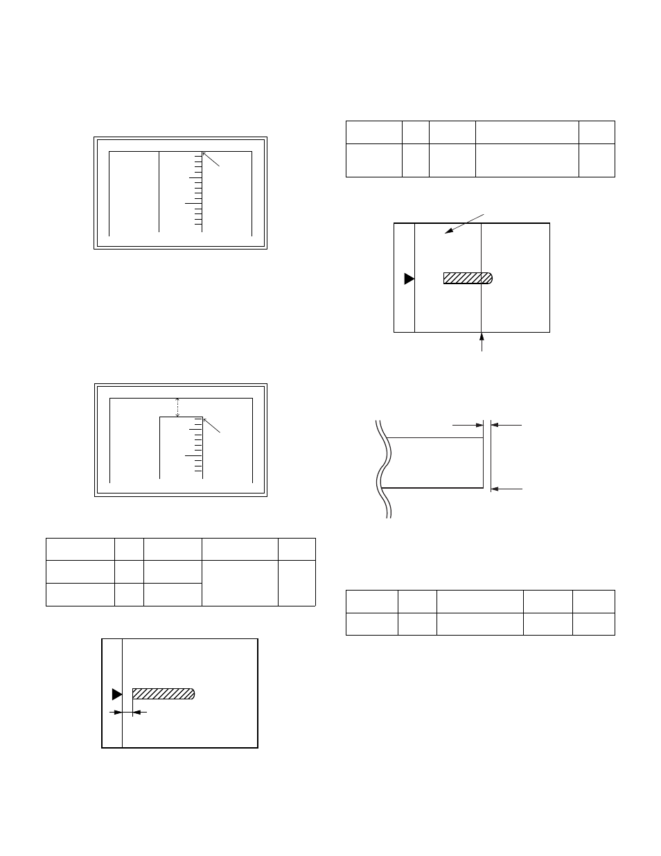
2) Measure the distance H between the paper lead edge and the
image print start position. Set the image print start position set
value again.
• 1 step of the set value corresponds to about 0.127mm shift.
• Calculate the set value from the formula below.
99 – H/0.127 (mm) = Image print start position set value
∗
Fit the print edge with the paper edge, and perform the lead
edge adjustment.
Example: 99 – 5/0.127 = 99 – 39.4 = about 59
Note: If the set value is not obtained from the above formula, per-
form the fine adjustment.
3) Execute SIM 50-1-2 to adjust the main cassette lead edge void.
• 1 step of the set value corresponds to about 0.127mm shift.
• Calculate the set value from the formula below.
B/0.127 (mm) = Lead edge void adjustment value
Example: When setting the lead edge void to 2.5mm:
2.5 /0.127 = about 20
(3) SPF image lead edge position adjustment
1) Set a scale on the OC table as shown below.
Note: Since the printed copy is used as a test chart, put the scale in
paralleled with the edge lines.
2) Make a copy, then use the copy output as an original to make an
SPF copy again.
3) Check the copy output. If necessary, perform the following adjust-
ment procedures.
4) Execute SIM 50-6.
5) Set the SPF lead edge position set value so that the same image is
obtained as that obtained in the previous OC image lead edge
position adjustment.
(4) Rear edge void adjustment
1) Set a scale as shown in the figure below.
2) Set the document size to A4 (8.5" x 11"), and make a copy at
100%.
3) If an adjustment is required, follow the procedures below.
4) Execute SIM 50-1 and set the density mode to DEN-B. The cur-
rently set adjustment value is displayed.
5) Enter the set value and press the start key.
The correction value is stored and a copy is made.
(5) Paper off center adjustment
1) Perform this adjustment after execution of SIM 48-3.
2) Set a test chart (UKOG-0089CSZZ) on the document table.
3) Select a paper feed port and make a copy.
Compare the copy and the test chart. If necessary, perform the follow-
ing adjustment procedure.
4) Execute SIM 50-10.
Select the mode with the arrow keys, enter the adjustment value
with the 10-key, and press the [OK] key.
Pressing the [START] key makes a print.
Pressing the [RETURN] key returns to the mode selection.
Adjustment
mode
SIM
Set value
Spec value
Setting
range
Main cassette
lead edge void
50-1-
2
B/0.127
Lead edge void:
1 to 4mm
Image loss: 3mm
or less
1 – 99
Print start
position
50-5
99 – H/0.127
5
10
0mm
0mm
5
10
2.5mm
2.5mm
Adjustment
mode
SIM
Set value
Spec value
Setting
range
SPF image
lead edge
position
50-6 1 step:
0.127mm
shift
Lead edge void:
1 – 4mm
Image loss: 3mm or less
1 – 99
Adjustment
mode
SIM
Set value
Spec
value
Setting
range
Rear edge
void
50-1-6
1 step: 0.127mm
shift
4mm or
less
1 – 99
A4 (8.5" x 11")
Paper rear edge
Void amount (Standard value: 4mm or less)
Scale image
Paper rear edge