JVC Model 200 User Manual
Page 73
Chapter 2---System Description
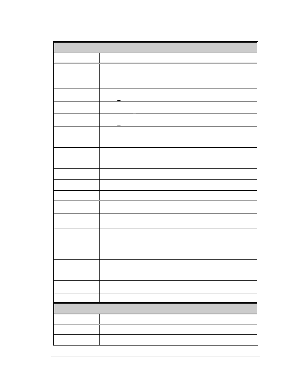
Table 2-15. Scan Reversal Board I/O signals
Horizontal / Vertical Deflection Board
INPUTS DESCRIPTION
H_OUT_
FLYBACK
Horizontal output flyback pulse, about 800 VPP
H_LOCK+
Horizontal interlock for yoke connectors. This should be about 5
V when closed or 15 V when open.
H_RED+
Output of horizontal red centering (also top of the red horiz yoke).
About + 5 Vdc.
H_GRN+
Output of horizontal green centering (also top of the green horiz
yoke). About + 5 Vdc.
H_BLU+
Output of horiz. blue centering (also top of the blue horiz yoke).
About + 5 Vdc.
V_RED+
Output of red vertical amplifier. about 40 VPP
V_GRN+
Output of green vertical amplifier. about 40 VPP
V_BLU+
Output of blue vertical amplifier. about 40 VPP
+15 V
+15 volt supply for use by SRB
+5 V
+5 volt supply for use by SRB
-15 V
-15 V supply for use by SRB
OUTPUTS DESCRIPTION
H_LOCK-
Horizontal interlock for yoke connectors. It should be 5 V when
closed or 0 V when open.
V_RED-
V_RED_SENS
Current feedback of red vertical amplifier
V_GRN-
V_GRN_SENS
Current feedback of green vertical amplifier
V_BLU-
V_BLU_SENS
Current feedback of blue vertical amplifier
FRONT/REAR
Front or rear projection status line. Front = low and rear = high
FLOOR/CEIL
Floor or ceiling status line. Floor = low and ceiling = high
H_CUR_FDBK
Horizontal current feed back, a DC signal proportional to horz.
output current
DEFL_OK
Deflection status line high (about 2 V) = good low = no scan
Convergence/Deflection Board
INPUTS DESCRIPTION
X_RED+
Output of horizontal red convergence amplifier
X_GRN+
Output of horizontal green convergence amplifier
Model 200 Service Manual
2-59