JVC Model 200 User Manual
Page 63
Chapter 2---System Description
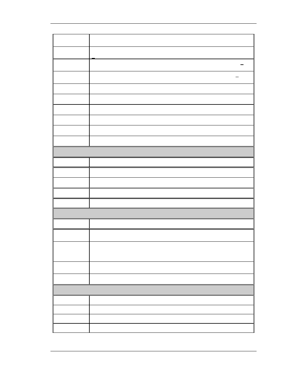
H_LOCK+
Horizontal interlock for yoke connectors. This should be about 5 V
when closed or 15 V when open.
H_RED+
Output of horiz. red centering (also top of the red horiz. yoke). About
+ 5 VDC.
H_GRN+
Output of horz. green centering (top of green horz. yoke). About + 5
VDC
H_BLU+
Output of horiz. blue centering (top of blue horiz. yoke). About + 5
VDC.
V_RED+
Output of red vertical amplifier. About 40 VPP.
V_GRN+
Output of green vertical amplifier. About 40 VPP.
V_BLU+
Output of blue vertical amplifier. About 40 VPP.
+15 V
+15 V supply for use by Scan Reversal Board
-15 V
-15 V supply for use by Scan Reversal Board
+5 V
+5 V supply for use by Scan Reversal Board
Convergence/Deflection Board
INPUTS DESCRIPTION
V_RAMP
Vertical ramp waveform. About 4 VPP.
V_PARAB
Vertical parabola waveform. About 4 VPP.
OUTPUTS DESCRIPTION
WIDTH_CTRL
A DC waveform for controlling width of picture. About 4 V max.
Raster Timing Generator (RTG board)
INPUTS DESCRIPTION
/H_ENABLE
A low on this line enables horizontal deflection. A high disables the
horizontal amplifier.
H_BAND:0
H_BAND:1
H_BAND:2
Horizontal frequency band line. 000 = band A, 001 = band B, 011 =
band C and 111 = band D.
HF_2V
Horizontal frequency to voltage converter. a DC signal proportional
to horiz. frequency. About 4.2 V at 90 kHz.
H_DRIVE
Horiz. drive pulse, 50 % duty cycle HCT level signal
System Power Supply
INPUTS DESCRIPTION
+5 V
+ 5 V supply for use by HVD and Scan Reversal Boards
+15 V
+ 15 V supply for use by HVD and Scan Reversal Boards
-15 V
- 15 V supply for use by HVD and Scan Reversal Board
Model 200 Service Manual
2-49