11 video input cards (vics) – JVC Model 200 User Manual
Page 110
Chapter
4---Maintenance
(Removal/Replacement)
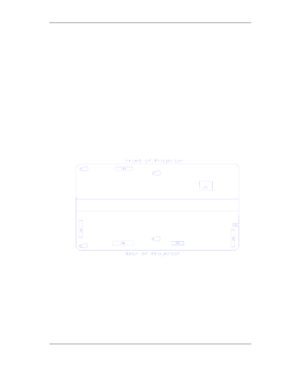
2. Disconnect 6 connectors; J34, J35, J36, J41, J42, and
J43. (see Figure 4-8). Move the cables out of the way.
3. Loosen (not necessary to remove) the 5 pozidrive screws
that secure the H/V Deflection Board to the electronic
module cage.
4. Remove the H/V Deflection PCB by sliding it toward the
left side of the projector (this is the upward direction if the
electronic module is raised up) so that the mounting
screws clear the access holes. Then lift the side of the
board that is nearest the front of the projector first and
angle it upward so that the side closest to the rear clears
the lip of the electronic module frame. Be careful when
removing or reinstalling the board to avoid gouging it on
the fan screws or cable clamps.
5. Reinstall the HV Deflection PCB by lowering the side that
is nearest to the rear of the projector in first until it clears
the electronic module edge, then lowering the other side.
Carefully fit the board over the mounting screws and slide
the board into position. Tighten the screws and reconnect
the connectors.
Figure 4-8. Horizontal/Vertical Deflection PCB.
4.11 Video Input Cards (VICs)
The 4 types of Video Input Cards, RGB Standard, 4X RGB Mux (4
RGB Input), Quad Decoder, and HDTV (YPbPr) are all removed and
inserted in the same manner.
To remove a VIC:
1. Disconnect all video input connections from the VIC to be
removed.
Model 200 Service Manual
4-13