JVC Model 200 User Manual
Page 57
Chapter 2---System Description
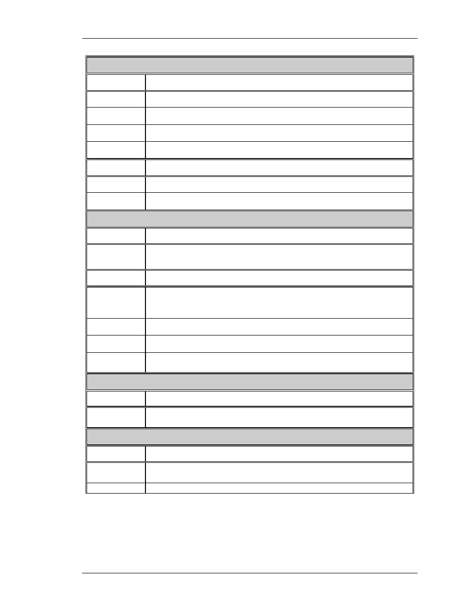
Video Processor Board
INPUTS DESCRIPTION
V_SYNC
Input vertical sync
H_SYNC
Input horizontal or composite sync
G_SYNC
Sync on green signal which is stripped for the green video
GRN_INPUT Buffered version of green video
OUTPUTS DESCRIPTION
Clamp
A negative going video clamp signal with about 3 % duty cycle
Blanking
Blanking signal composed of right, left, top and bottom blanking
Horizontal/Vertical Deflection Board
INPUTS DESCRIPTION
/H_
FLYBACK
Not used by the RTG board
OUTPUTS DESCRIPTION
H_BAND0
H_BAND1
H_BAND2
Horizontal frequency band lines
Band A = 000, Band B = 001, Band C = 011 and band D = 111
/H_ENABLE
Low = enabled deflection and high = disabled deflection
H_F2V
A DC voltage proportional to horizontal frequency
H_DRIVE
Square wave 50 % duty cycle synchronized to the selected
horizontal sync.
High Voltage Power Supply
OUTPUT DESCRIPTION
HVPS_
SYNC
Synchronization pulse for HVPS, synchronized with the selected
horiz. sync at either same, half or one third the frequency
ConvergenceDeflection Board
OUTPUT DESCRIPTION
V_DRIVE
Square wave negative going pulse synchronized to the selected
vertical sync with pulse width of about 4 horizontal periods
Model 200 Service Manual
2-43