JVC Model 200 User Manual
Page 40
Chapter 2---System Description
I
RED_G2
Red G2 Control
I
GRN_G2
Green G2 Control
I
BLU_G2
Blue G2 Control
I
WHT_BOOST
Gamma correction
I BLK_BOOST
Gamma
correction
I
G1_BIAS
G1 bias level
O
/VA_OK
Issues to SCB that Video Amplifier
is OK
O
BEAM_CURRENT
Beam current control
O
OK_DETECT
Issues to SCB that VPB is OK
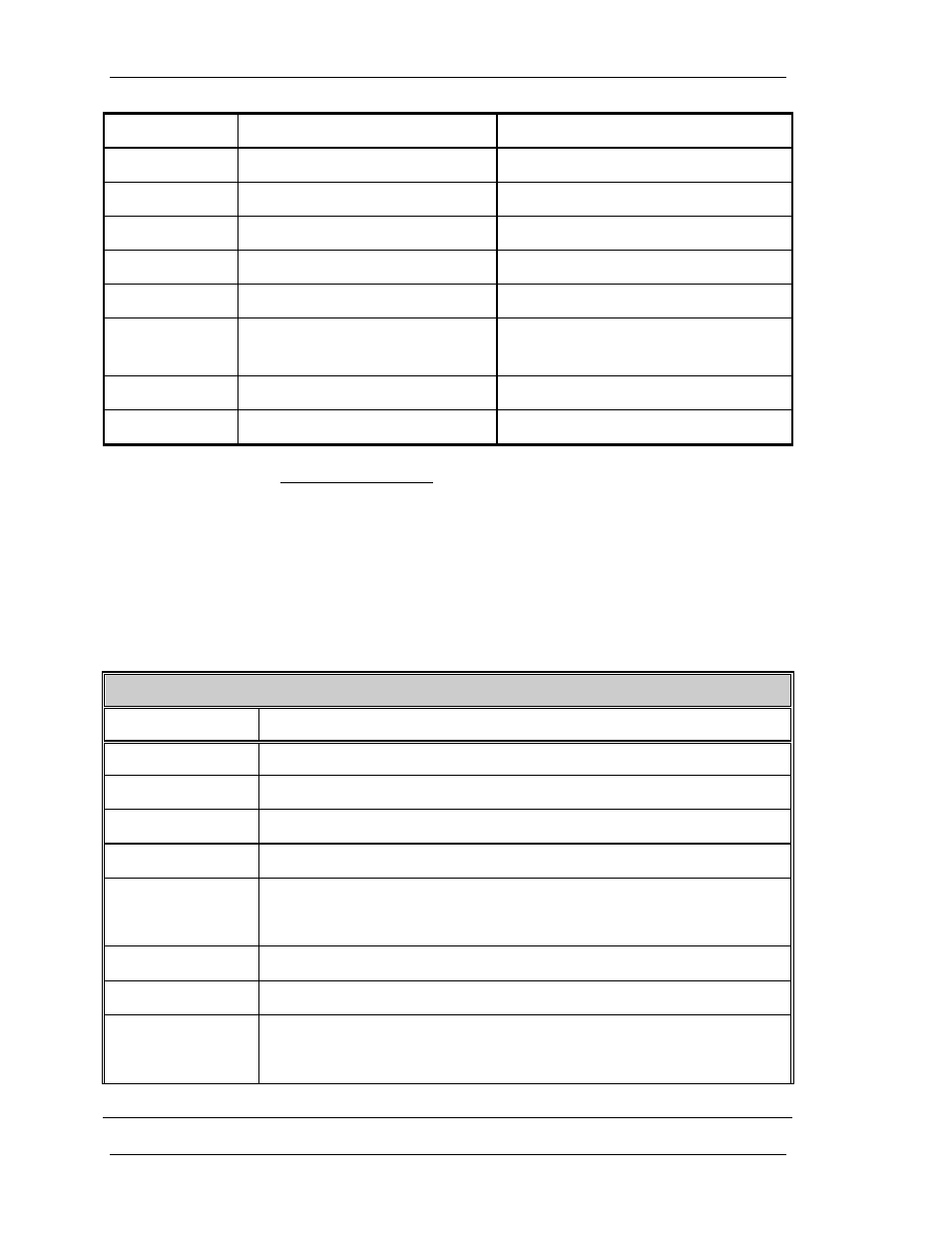
Video Processor I/O
This section provides a comprehensive description of the inputs to
and outputs from the VPB. The I/O descriptions in Table 2-7 are
arranged by the source/destination of the signal. The format used
is such that the assembly communicated with is used as the
primary heading of each group of signals. Those signals are
further subdivided into inputs and outputs. Inputs refers to an input
to the VPB, while output refers to an output from the VPB.
Table 2-7. Video Processor I/O signals
System Controller Board
INPUT DESCRIPTION
RED_OVER
Red signal of on-screen menu and/or internal test pattern
GRN_OVER
Similar to RED_OVER
BLU_OVER
Similar to RED_OVER
OVERLAY
Overlay control signal
RED_SENS
Sensitivity correction information for red. Real time data at
0 volt to 1 volt.
GRN_SENS
Similar to RED_SENS
BLU_SENS
Similar to RED_SENS
RED_THRES
Threshold correction information for red. Real time data at
0 Volt to 1 Volt
2-26
Model 200 Service Manual