Chapter 2---system description – JVC Model 200 User Manual
Page 49
Chapter 2---System Description
P11
B23
B24
B28
B29
B32
B27
B26
B31
B30
Lens Zoom
Lens Focus
/LV_ENA
/FAN_ENA
/LAMP_ENA
/HV_OK
/LV_OK
/LAMP_LIT
/LAMP_OK
P10
B31
B30
A32
A31
A30
A B
20-20
21-21
22-22
23-23
24-24
25-25
26-26
27-27
28-28
29-29
+5.1V stby
+5.1V
+15V
-15V
G N D
ODD_FIELD
SRC_VALID
H_DRIVE_SC
V_DRIVE
B9
B10
B2
B1
B3
RED_OVER
GRN_OVER
BLU_OVER
B18
B17
B16
P10
Y_RED_CONV
Y_GRN_CONV
Y_BLU_CONV
X_RED_CONV
X_GRN_CONV
X_BLU_CONV
B4
B5
B6
B1
B2
B3
BLU_THRES
GRN_THRES
RED_THRES
BLU_SENS
GRN_SENS
RED_SENS
B8
B9
B10
B11
B12
B13
IIC_DATA
IIC_CLK1
IIC_CLK
IIC_CLK3
IIC_CLK2
SYSTEM
CONTROLLER
BOARD
TO PROJ
LENS
FROM
LVPS
FROM
HVPS
FROM
ALPS
FROM
RTG
FROM
LVPS
TO
VPB
TO
CDB
TO
VPB
H_F2V
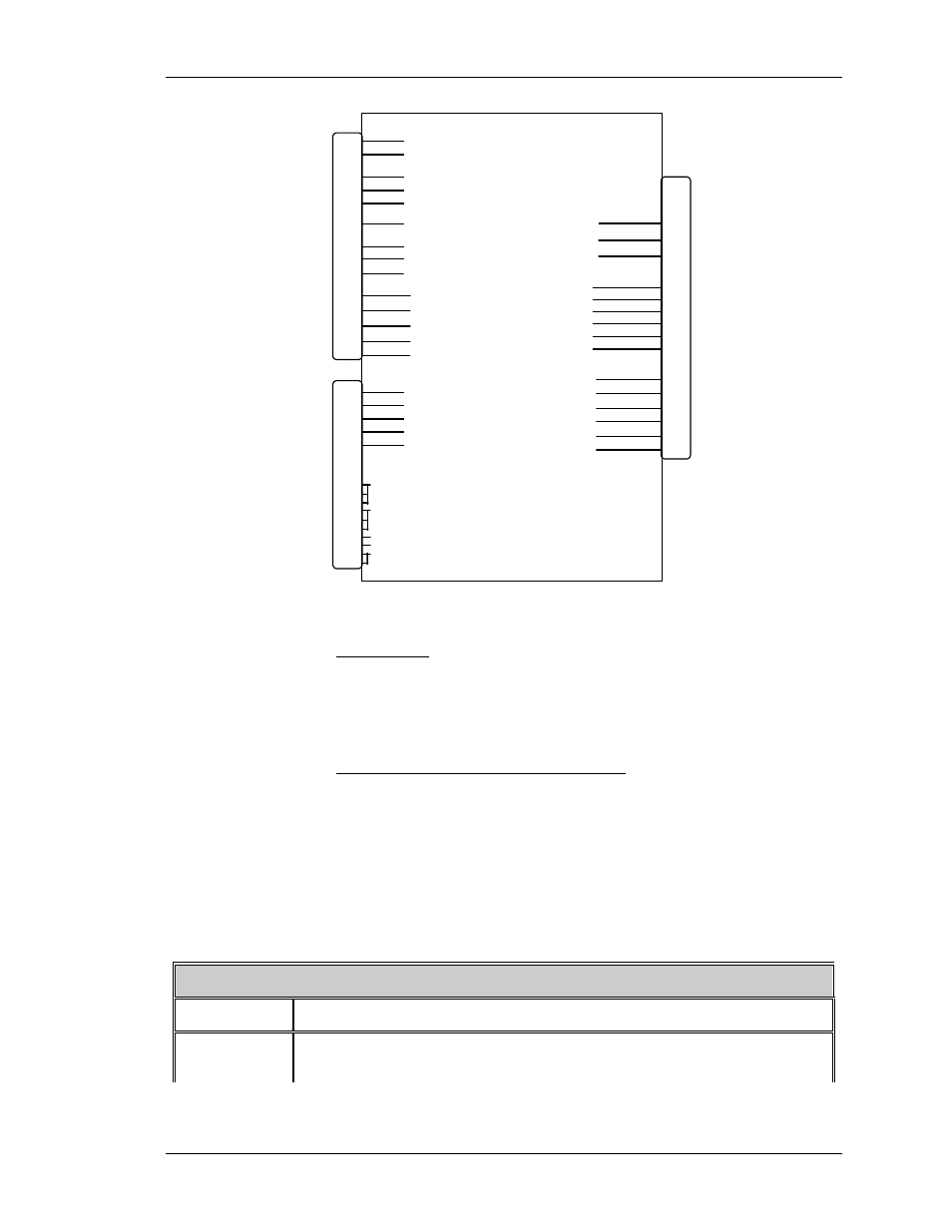
Figure 2-12. System Controller Board, Block Diagram.
IIC Interface
Communications are performed through the IIC bus to the other
PCBs in the system.This three wire bus interface consists of clock
line, data line and interrupt line. Data transferred over the IIC bus
is listed in Table 2-9 (I/O signals).
System Controller Board Input/Output
This section provides a description of the inputs to and outputs
from the SCB. The I/O descriptions are arranged by the
source/destination of the signal. The format used is such that the
assembly communicated with is used as the primary heading of
each output. Input refers to an input to the SCB, output refers to
an output from the SCB.
Table 2-9. System Controller Board I/O signals
Video Processor Board
I/O DESCRIPTION
IIC_CLK
IIC clock line. Clock line for control of synchronous data transfer over
the IIC bus interface.
Model 200 Service Manual
2-35