JVC Model 200 User Manual
Page 52
Chapter 2---System Description
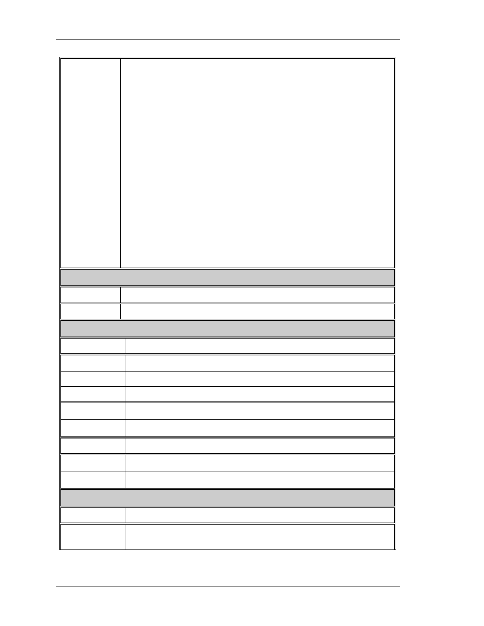
IIC_DATA
IIC data line. Bidirectional serial line for synchronous data transfer
between the SCB and the Horizontal/Vertical Deflection board.
I=Input, O=Output.
O V_RED_LIN_CONTROL
O V_GRN_LIN_CONTROL
O V_BLU_LIN_CONTROL
O V_RED_EDGE_CONTROL
O V_GRN_EDGE_CONTROL
O V_BLU_EDGE_CONTROL
O L/R_KEY_CONTROL
O L/R_PIN_CONTROL
O WIDTH_CONTROL
O H_RED_CENT_CONTROL
O H_GRN_CENT_CONTROL
O H_BLU_CENT_CONTROL
O V_RED_CENT_CONTROL
O V_GRN_CENT_CONTROL
O V_BLU_CENT_CONTROL
O FRONT/REAR
O FLOOR/CEIL
High Voltage Power Supply
INPUT DESCRIPTION
/HV_OK
The high voltage status line. Low = operational HVPS.
Low Voltage Power Supply
INPUTS DESCRIPTION
+ 5.1V
Power for digital portion of SCB
+15V
Power for the analog portions of the SCB
-15V
Power for the analog portions of the SCB
+5.1V_Stby
Standby power to the CPU and peripherals.
/LV_OK
Tells SCB status of non-standby supply (all outputs working or not)
OUTPUTS DESCRIPTION
FAN_ENA
Signal to enable the 24V standby power
LV_ENA
Signal to enable the LVPS
Arc Lamp Power Supply
INPUTS DESCRIPTION
/LAMP_OK
Informs SCB that the Arc Lamp is installed, temperature is within
limits, and lamp cooling blower is working
2-38
Model 200 Service Manual