JVC Model 200 User Manual
Page 51
Chapter 2---System Description
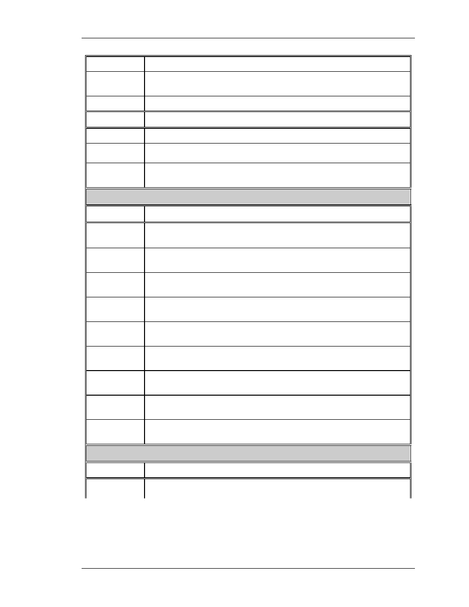
H_DRIVE
Square wave 50% duty cycle synchronized to selected horiz sync
V_DRIVE
Square wave negative going pulse synchronized to selected vertical
sync with pulse width of about 4 horiz lines
H_F2V
DC voltage proportional to horiz frequency
OUTPUTS
DESCRIPTION
ISYNC_CLK
5 mHz clock used to generate the internal sync signals
IIC_CLK
IIC clock line. Unidirectional clock line for control of synchronous
data transfer over the IIC bus interface.
IIC_DATA
IIC data line. Bidirectional serial line for synchronous data transfer
between System Controller and RTG.
Convergence/Deflection Board
OUTPUTS DESCRIPTION
IIC_CLK
IIC clock line. Unidirectional clock line for control of synchronous
data transfer over the IIC bus interface.
IIC_DATA
IIC data line. Bidirectional serial line for synchronous data transfer
between the SCB and the Convergence/Deflection board.
X_RED_
CONV
Red X convergence waveform. The amplitude for full scale correction
is about 1 VPP.
X_GRN_
CONV
Grn X convergence waveform. The amplitude for full scale correction
is about 1 VPP.
X_BLU_
CONV
Blu X convergence waveform. The amplitude for full scale correction
is about 1 VPP.
Y_RED_
CONV
Red Y convergence waveform. The amplitude for full scale correction
is about 1 VPP.
Y_GRN_
CONV
Grn Y convergence waveform. The amplitude for full scale correction
is about 1 VPP.
Y_BLU_
CONV
Blu Y convergence waveform. The amplitude for full scale correction
is about 1 VPP.
CORR_
SYNC
Square wave HCT level synchronous signal for horiz axis.
Horizontal/Vertical Deflection Board
OUTPUTS DESCRIPTION
IIC_CLK
IIC clock line. Unidirectional clock line for control of synchronous
data transfer over the IIC bus interface.
Model 200 Service Manual
2-37