JVC Model 200 User Manual
Page 42
Chapter 2---System Description
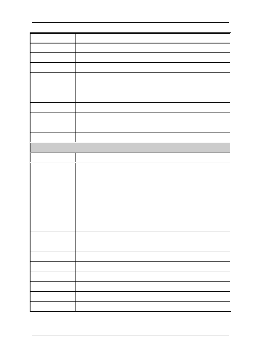
OUTPUT DESCRIPTION
RED_VIDEO
Red video output. 0 Volt to 1 Volt.
GRN_VIDEO
Similar to RED_VIDEO
BLU_VIDEO
Similar to RED_VIDEO
RESTORE
DC RESTORE control signal. When this signal is asserted, the
DC level of the video signal is clamped at the proper value
on the VAB.
RED_G2
Red CRT G2 voltage adjust control signal.
GRN_G2
Similar to RED_G2
BLU_G2
Similar to RED_G2
G1_BIAS
Control the adjustment of G1 voltage for all three CRTs
External Video
INPUT
DESCRIPTION
RED_VIC #1
Red video input from video input card #1
GRN_VIC #1
Similar to RED_VIC #1
BLU_VIC #1
Similar to RED_VIC #1
RED_VIC #2
Similar to RED_VIC #1
GRN_VIC #2
Similar to RED_VIC #1
BLU_VIC #2
Similar to RED_VIC #1
RED_VIC #3
Similar to RED_VIC #1
GRN_VIC #3
Similar to RED_VIC #1
BLU_VIC #3
Similar to RED_VIC #1
H_VIC #1
Horizontal sync signal input from video input card #1
H_VIC #2
Similar to H_VIC #1
H_VIC #3
Similar to H_VIC #1
V_VIC #1
Vertical sync signal input from video input card #1
V_VIC #2
Similar to V_VIC #1
V_VIC #3
Similar to V_VIC #1
2-28
Model 200 Service Manual