JVC Model 200 User Manual
Page 33
Chapter 2---System Description
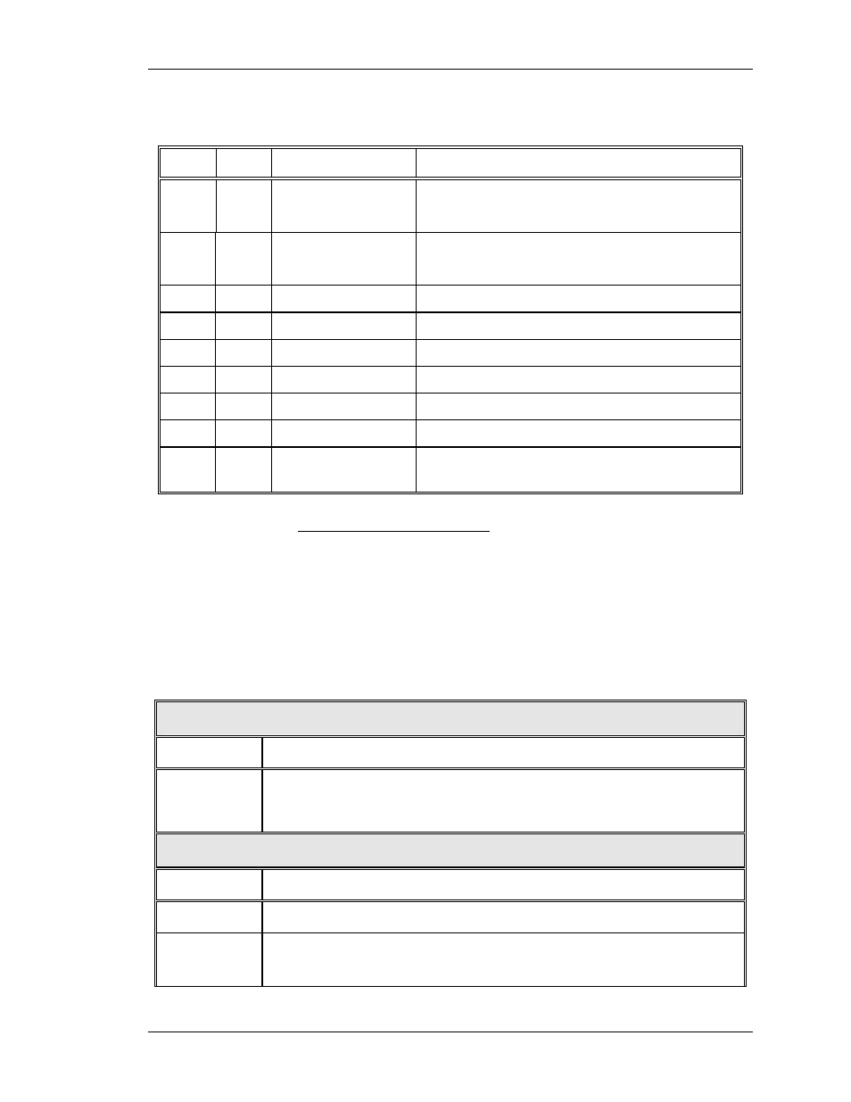
Table 2-4. HDTV VIC IIC Interface
I/O
Bits
Information
Description
I
1
/SEL_YPbPr
Selects YPbPr input mode for the YPbPr_VIC.
Low = Selected YPbPr input mode.
I
1
/SEL_RGB
Selects RGB input mode for the YPbPr_VIC.
Low = Selected RGB input mode.
I
8
GAMMA
Data for adjustment of Gamma correction
I
8
COLOR
Data for adjustment of color
I
8
HUE
Data for adjustment of hue
I
8
SHARPNESS
Data for adjustment of sharpness
O
4
VIC_ID
VIC identification lines. 0001 for YPbPr_VIC
O
1
VIC_MODEL
Revision of the YPbPr_VIC.
O
1
/YPbPr_OK
YPbPr_VIC status line. Low = operational
YPbPr_VIC
The HDTV YPbPr_VIC I/O
This section provides a comprehensive description of the inputs to
and outputs from the YPbPr_VIC. The I/O descriptions are
arranged by the source/destination of the signal. The format used
is such that the assembly communicated with is used as the
primary heading of each group of signals. Those signals are
further subdivided into inputs and outputs. Input refers to an Input
to the YPbPr_VIC, output refers to an output from the YPbPr_VIC.
Table 2-5. HDTV VIC Signals
Projector Inputs
INPUT
DESCRIPTION
Y/G
Pb/B
Pr/R
Video input signals-about 0.7 to 1 VPP
Video Processor Board
OUTPUT
DESCRIPTION
/SELECT
Selection indicator for VIC. Low indicates the selected YPbPr_VIC.
RED
GRN
BLU
Video signals. about 0.7 to 1 VPP
Model 200 Service Manual
2-19