Example scenario, Figure 5: bridging network with mx series routers – Juniper Networks JUNOS OS 10.4 User Manual
Page 43
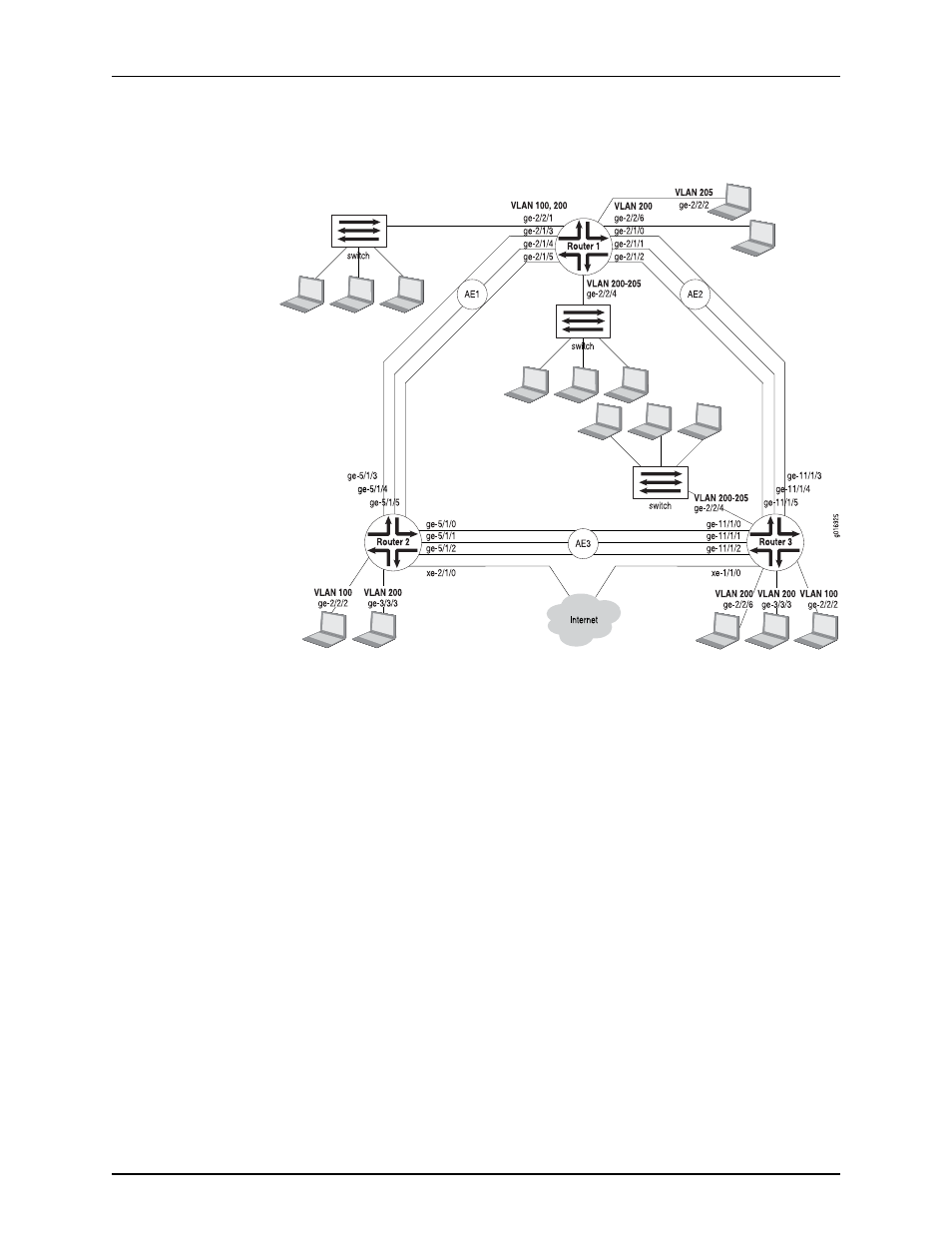
Figure 5: Bridging Network with MX Series Routers
The three routers each have a series of hosts on their Ethernet interfaces, as well as
aggregated Ethernet links between them. Router 2 and Router 3 are linked to the Internet,
and Router 1 and Router 3 are also linked to switches configured with a range of VLANs,
as shown in the figure. Because the VLAN tags are important, the routers run Multiple
STP (MSTP) on the links connecting them to prevent bridging loops (Rapid STP, or RSTP,
does not recognize VLAN tags and blocks ports without regard for VLAN tagging).
Example Scenario
The network administrator wants to configure these links and devices so that:
•
The six Gigabit Ethernet links between Router 1 and the other routers (
ge-2/1/0
through
ge-2/1/5
) are gathered into two aggregated Ethernet (AE) links mixing bridged traffic
from the VLANs.
AE1
will consist of the first three links and
AE2
will use the last three
links. The same approach is taken for the links on Router 2 and Router 3.
•
The Gigabit Ethernet links from Router 1 to the customer devices (
ge-2/2/1
and
ge-2/2/6
) will be bridged and include VLAN tag 100 on
ge-2/2/1
and VLAN tag 200 on
ge-2/2/6
.
The other two routers, Router 2 and Router 3, also have two ports configured to handle
VLAN 100 on one port (
ge-2/2/2
) and VLAN 200 on the other (
ge-3/3/3
).
•
Router 2 and Router 3 have IRB configured so that they can pass traffic to other routers
in the rest of the network.
23
Copyright © 2013, Juniper Networks, Inc.
Chapter 2: Basic Layer 2 Features on MX Series Routers