Routers, Table 5: components of the network topology – Juniper Networks JUNOS OS 10.4 User Manual
Page 182
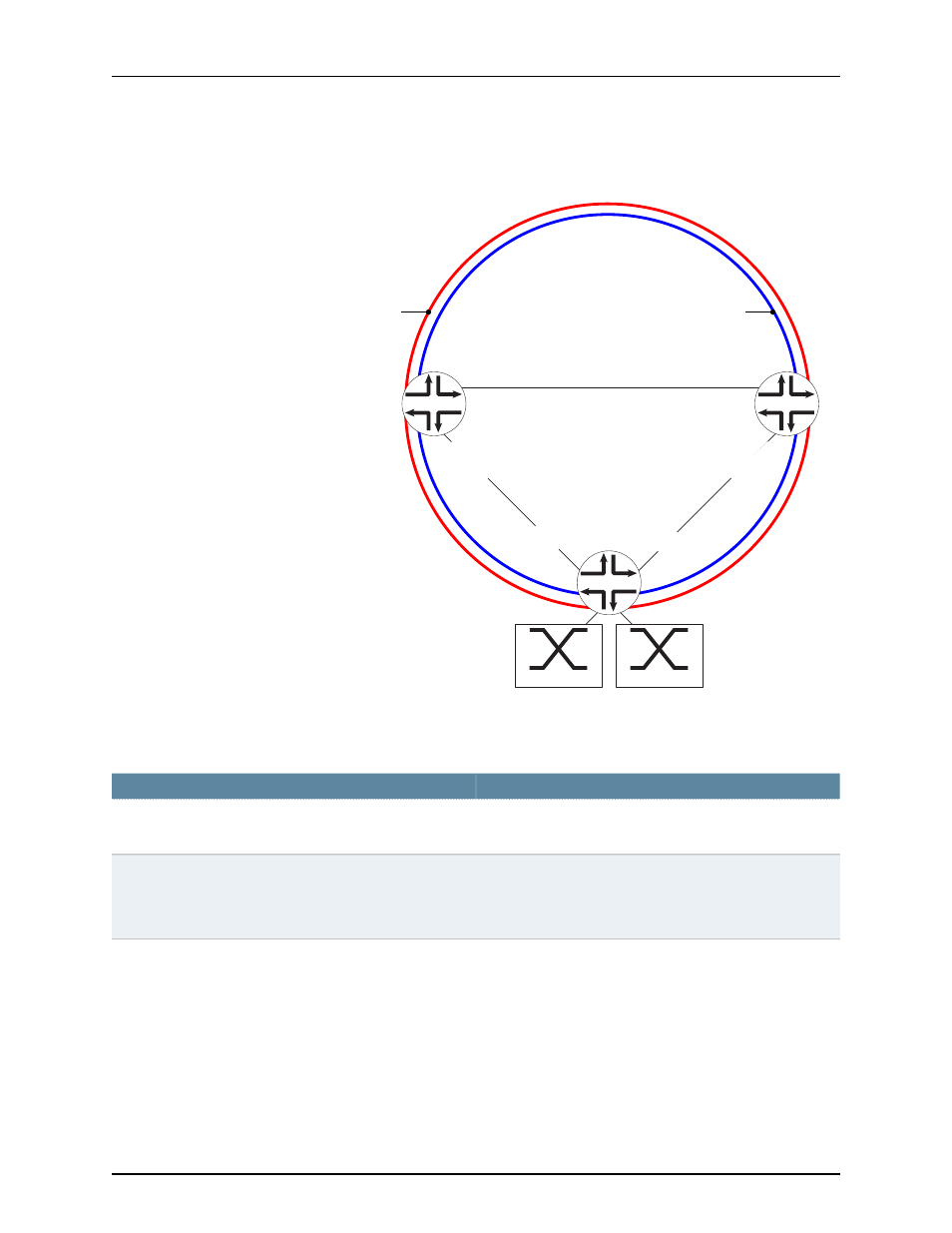
Figure 24: ERP with Multiple Protection Instances Configured on Three
MX Series Routers
AS1
CS1
CS2
g017469
ge-5/2/3.0
west-interface
ge-2/0/4.0
east-interface
ring-1
data-channel [200,300]
ring-2
data-channel [500,600]
RPL owner
ring-1
ge-3/2/4.0
east-interface
RP link end ring-1
ge-2/0/8.0
west-interface
RP link end ring-2
ge-2/0/5.0
west-interface
ge-2/1/1.0
east-interface
RPL owner
ring-2
Customer Site 2
VLANs [500,600]
Customer Site 1
VLANs [200,300]
describes the components of the example topology.
Table 5: Components of the Network Topology
Settings
Property
•
ring-1
—Data channel [200,300]
•
ring-2
—Data channel [500,600]
Ring instances
Two customer sites are connected to AS 1:
•
Customer site 1, VLAN 200 and VLAN 300
•
Customer site 2, VLAN 500 and VLAN 600
Customer sites
Copyright © 2013, Juniper Networks, Inc.
162
Junos OS 13.1 MX Series 3D Universal Edge Routers Solutions Guide