Alarm input/output terminal connection, Alarm input terminal, Alarm output terminal – JVC VN-C20 User Manual
Page 17: Alarm input/output terminal connection 17, Alarm input terminal alarm output terminal, Cation, Input requirements, Output requirements
17
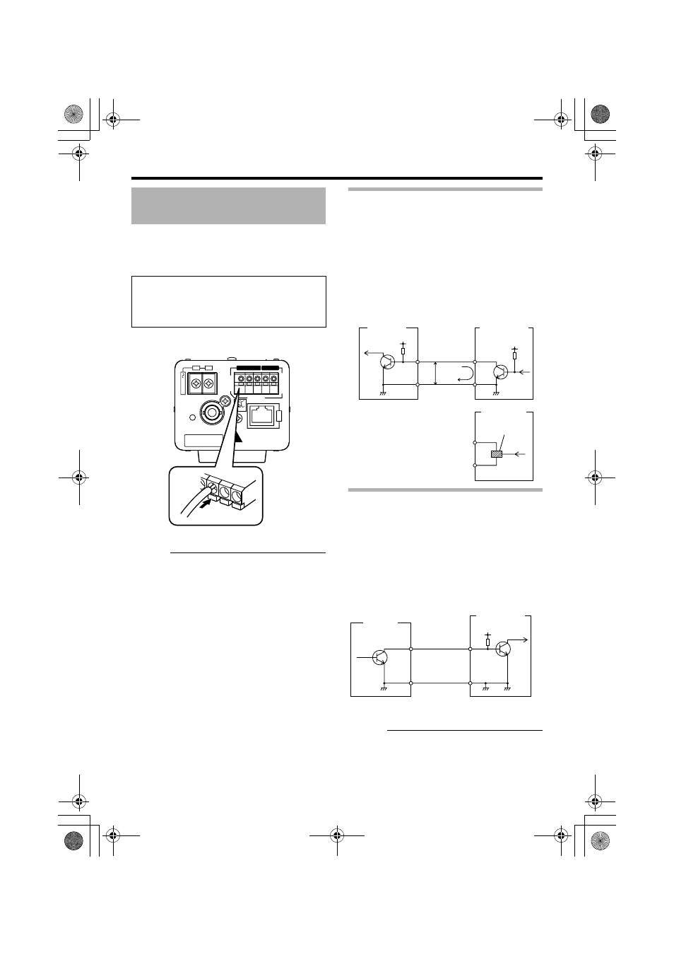
Connect the alarm input/output terminals with
external devices such as a sensor, buzzer, etc.
Plug/Unplug the cable by pressing the button as
shown in the diagram below.
Cation:
● Noises from an external source may cause
malfunctions even when the cable used in
shorter than 50 m. In this case, use a
shielded cable or move the cable away from
the noise source.
Alarm Input Terminal
Connect this terminal to sensor devices, such as an
infrared sensor, door sensor, metal sensor, manual
switch, etc.
Ⅵ Input requirements
● No-voltage relay NPN open collector input
● Polarity of input detection can be selected
using a software
● Make/Break (500 ms and above)
● Circuit current at low level: 0.3 mA
● Applied voltage at high level: 3.3 V
Alarm Output Terminal
Connect this terminal to annunciating devices, such
as annunciators, indicators, lights, buzzers, etc.
Ⅵ Output requirements
● Equivalent to NPN open collector output (Set
the output put logic via the Internet Explorer)
● Allowable applied voltage: DC12 V and below
● Allowable inflow current: 50 mA
● Momentary (100 ms to 5000 ms) output
(Set time via the Internet Explorer) (
Cation:
● Connect the G terminal of this camera to the
GND terminal of the annunciating device.
Alarm Input/Output Terminal
Connection
Cable to use
● Length of 50 m or shorter
● UL1007, UL1015 or equivalent products
● AWG#22 - AWG#18 or equivalent products
CLASS
2
ONL
Y
For
U
SA
ISOLA
TED
PO
WER
ONL
Y
For
E
UR
OPE
and
O
THER
POWER
CAUTION: Do not use
PoE and AC24V together
VIDEO OUT
10BASE-T/100BASE-TX
G
2
1
2
1
2
1
ALARM
OUTPUT
Po
E
INPUT
A
C24V
PUSH
DO NOT CONNECT TO THE
TELEPHONE NETWORK
Push
OUT
R
DC3.3V
GND
0.6mA
R
VCC
OUT
GND
3.3V
(Alarm Input Equivalent
Circuit)
Grounding
Terminal
INPUT
Terminal 1
or 2
VN-C20
Sensor
Connection
Example (1)
Sensor
Connection
Example (2)
Relay, switch,
etc.
IN
R
DC 12 V
GND
Alarm Device
Connection
Example
OUTPUT
Terminal 1
or 2
VN-C20
(Alarm Output
Equivalent Circuit)
Grounding
Terminal
VN-C20_EN.book Page 17 Tuesday, January 31, 2006 1:51 PM