IBM CI5VGM Series User Manual
Page 36
Chapter 2 Installations
32
CI5VGM User’s Manual
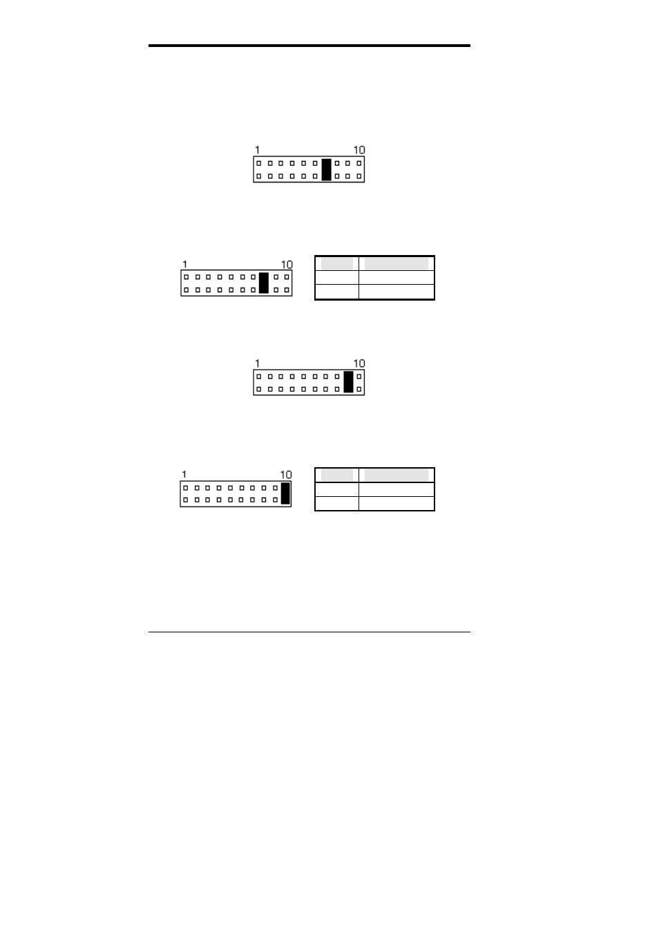
ATX Power ON Switch: Pins 7 and 17
This 2-pin connector is an “ATX Power Supply On/Off
Switch” on the system that connects to the power switch on
the case. When pressed, the power switch will force the
system to power on. When pressed again, it will force the
system to power off.
Turbo LED Connector: Pins 8 and 18
There is no turbo/deturbo function on the CPU card. The
Turbo LED on the control panel will always be On when
attached to this connector.
Pin #
Signal Name
8 5V
18 Ground
Reset Switch: Pins 9 and 19
The reset switch allows the user to reset the system without
turning the main power switch Off and then On.
Hard Disk Drive LED Connector: Pins 10 and 20
This connector connects to the hard drive activity LED on
control panel. This LED will flash when the HDD is being
accessed.
Pin #
Signal Name
10 HDD
20 5V
- ADSL Bridge/ Router Heritage (167 pages)
- 27L2579 (20 pages)
- DR550 (128 pages)
- LCD/LVDS/LAN (154 pages)
- 22P6959 (50 pages)
- ThinkPad 73P3315 (62 pages)
- ULTRABAY 2000 (62 pages)
- SYSTEM STORAGE DS4000 (38 pages)
- uPD78P083 (274 pages)
- 2257 (252 pages)
- 51 (248 pages)
- 2 (72 pages)
- System Storage N6040 (6 pages)
- 22P6960 (56 pages)
- 07N4108 (11 pages)
- 22P9176 (76 pages)
- 22P6972 (46 pages)
- 48X (60 pages)
- 22P6979 (52 pages)
- 8313 (314 pages)
- 19K4543 (56 pages)
- SC30-3865-04 (513 pages)
- DTLA-305020 (2 pages)
- WebSphere Adapters (226 pages)
- x Series 200 (152 pages)
- Storage Device Enclosure 7214 (4 pages)
- Tivoli and Cisco (516 pages)
- ZSERIES 890 (12 pages)
- 10K0001 (20 pages)
- 31P8128 (112 pages)
- 09N4076 (78 pages)
- Computer Drive (44 pages)
- N7000 (8 pages)
- All-in-One Super7 Single Board Computer PCM-5896 (128 pages)
- 20X (17 pages)
- 73P3309 (64 pages)
- W2H (68 pages)
- 22P6415 (62 pages)
- THINKCENTER 8187 (290 pages)
- NETVISTA 6830/6831 (152 pages)
- 802.11g Wireless Broadband Router WRT-410 (69 pages)
- THINKPAD 72 W DC (70 pages)
- ThinkPad 73P3279 (54 pages)
- HS64 (13 pages)
- THINKVISION MONITOR L150P (35 pages)