Front and right side, Back, Front and right side back – Insignia NS-PDP50HD-09 User Manual
Page 7
7
Insignia NS-PDP50HD-09 50" PDP TV
www.insignia-products.com
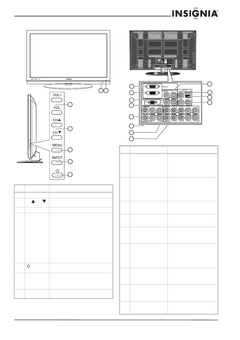
Front and right side
Back
#
Item
Description
1
VOL +/VOL -
Press to increase or decrease the volume.
2
CH
/
CH
Press to change to a higher or lower
channel.
3
MENU button
Press to open the on-screen menu.
4
INPUT button
Press to select the AV signal input. You can
select:
• TV (CABLE/AIR)
• VIDEO1 (REAR)
• S-VIDEO1 (REAR)
• VIDEO2 (SIDE))
• S-VIDEO2 (SIDE)
• YPbPr1
• YPbPr2
• HDMI1 (REAR)
• HDMI2 (REAR)
• HDMI3 (SIDE)
• PC (VGA).
5
(power)
button
Press to turn your TV on or off.
6
Power/Standby
indicator
Lights when your TV is plugged into a
power outlet. When your TV is on, the
indicator is blue. When your TV is in
standby mode, the indicator is red.
7
IR sensor
Receives signals from the remote control.
Do not block.
1
2
3
5
4
6 7
#
Description
Function
1
HDMI 1 IN
Connect an HDMI cable to this
connector. Supports HD video
and digital audio. Does not
support 480i. Accepts DVI video
using an adapter or HDMI-to-DVI
cable (not included).
2
HDMI 2 IN
Connect an HDMI cable to this
connector. Supports HD video
and digital audio. Does not
support 480i. Accepts DVI video
using an adapter or HDMI-to-DVI
cable (not included).
3
PC IN VGA
Connect a VGA (D-sub) cable
from your PC to this connector
(analog PC).
4
PC IN AUDIO L/R
Connect left (white) and right
(red) audio cables to the L and R
jacks.
5
S-VIDEO1 IN
(S-Video
and L/R audio)
Connect an S-Video cable and
connect left (white) and right
(red) audio cables to the L and R
jacks.
6
VIDEO1 IN (composite
video and L/R audio)
Connect a video cable (analog
composite video - 480i) to this
jack (yellow).
Connect left (white) and right
(red) audio cables to the L and R
jacks.
7
YPbPr1 IN, AUDIO L,
and AUDIO R
Connect component video cables
to the Y, Pb, and Pr jacks and
audio left (white) and right (red)
cables to the L and R jacks.
8
YPbPr2 IN, AUDIO L,
and AUDIO R
Connect component video cables
to the Y, Pb, and Pr jacks and
audio left (white) and right (red)
cables to the L and R jacks.
9
HDMI audio in
Connect left (white) and right
(red) audio cables to the L and R
jacks.
Y
Y
Pb
Pr
Pb
Pr
L
R
R
L
PC IN
VIDEO
L
R
L
R
Y/C
R
L
R
R
L
HDMI 2 IN
HDMI 3 IN
DIGITAL-AUDIO
VIDEO
OUTPUT
AV2 IN
AV4 IN
AV3 IN
AV5 IN
L
VGA
1
2
3
5
11
8
12
7
9
4
6
10