4 post code debugger, 5 clock generation, Table 4. system clocks – Intel 915GME User Manual
Page 28: 6 power management states, Keyboard/mouse, 32 bit/33 mhz pci connectors, Ethernet 10/100 lan interface connector, Lvds flat panel display interface, Post code debugger, Clock generation
Mobile Intel
®
915GME Express Chipset —Theory of Operation
Mobile Intel
®
915GME Express Chipset
Development Kit User’s Manual
April 2007
28
Order Number: 317230-001US
3.4.3.6
Keyboard/Mouse
The keyboard and mouse connectors are PS/2 style, six-pin stacked miniature DSUB
connectors. The top connector is for the mouse and the bottom connector is for the
keyboard.
3.4.3.7
32 bit/33 MHz PCI Connectors
Two industry standard 32 bit/33 MHz PCI connectors are provided on the evaluation
board. These slots support 3.3 V and 5 V devices.
3.4.3.8
Ethernet 10/100 LAN Interface connector
The evaluation board provides support for one Industry standard 10/100 RJ45 LAN
Interface Connector (Integrated with the dual USB connector).
3.4.3.9
LVDS Flat Panel Display Interface
The evaluation board provides support for one forty-four pin LVDS video interface
connector. The provided LVDS connects to most flat panel display assemblies.
3.4.4
Post Code Debugger
A port 80-83 display at CR6A1, CR6A2, CR6A3, and CR6A4 show cycles and can be
used for debug information during POST. The evaluation board uses an AMI* BIOS.
For AMI* BIOS POST codes, please visit:
3.5
Clock Generation
The Mobile Intel
®
915GME Express Chipset board uses a CK-410M and CK-SSCD
compatible solution. The FSB frequency is determined from decoding the processor
BSEL settings.
The clock generator provides Processor, GMCH, ICH6-M, PCI, PCI Express, SATA, and
USB reference clocks. Clocking for DDR2 is provided by the GMCH.
3.6
Power Management States
The evaluation board supports S1 (Stop Grant), S3 (Suspend to RAM), S4 (Suspend to
disk), and S5 (Soft-off) states. Transition requirements are detailed below.
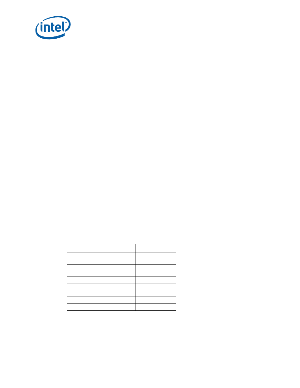
Table 4.
System Clocks
Clock Name
Speed
CPU
133 MHz @ 533
100 MHz @ 400
DDR2
100 MHz @ 400
133 MHz @ 533
PCI Express and DMI
100 MHz
SATA
100 MHz
PCI
33 MHz
Audio
14 MHz
USB
48 MHz