Step 0600-012, Fan failure diagnostics -8 – IBM RS/6000 SP User Manual
Page 28
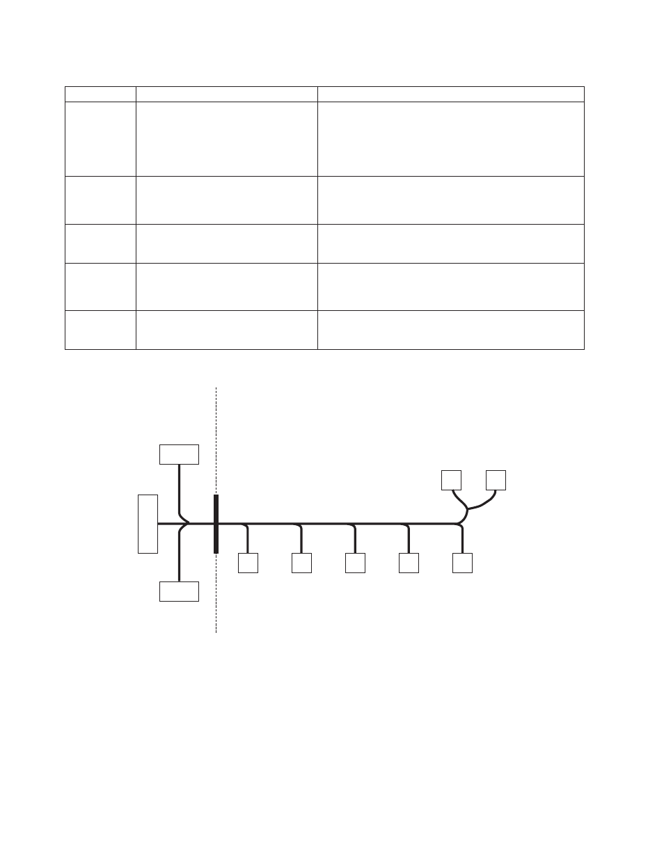
Table 1-4. Fan failure diagnostics
Priority
Component
Action
1
(1 of 5)
Fan 1, 2, 3, 4 or 5
a. Check specified fans for blockages or loose cable
connections.
b. Fix any obvious problems and continue at “Step
c. If you do not find any problems, continue at Priority 2.
2
(2 of 5)
Fan 1, 2, 3, 4 or 5
a. Replace fans as described in Chapter 4, “FRU
removals and replacements” on page 4-1.
b. Continue at “Step 0600-012”.
3
(3 of 5)
Switch supervisor card
a. Replace the card.
b. Continue at “Step 0600-012”.
4
(4 of 5)
Switch supervisor control cable
a. Replace the cable. Refer to Figure 1-3, for cable
connections.
b. Continue at “Step 0600-012”.
5
(5 of 5)
All replaced
Call next level of support.
Step 0600-012
You performed the recommended action in Table 1-4.
1. Component replaced or reseated.
2. Reconnect all cables inside the SP Switch.
3. Install front panel assembly and reinstall front retaining screws (see “Service position procedures” on
4. Connect only power (J1) and supervisor (J2) cables at the rear of the SP Switch.
5. Put the SP Switch’s circuit breaker into the On (‘1’) position.
P2 (Fan 1)
2 x 2
P6 (Power Card)
2 x 1
P4 (Power Card)
2 x 1
Front Chassis Cable
Inner Chassis Cable
P5
(Switch SV Card)
2 x 20
P1
P3
P3 (Fan 2)
2 x 2
P4 (Fan 3)
2 x 2
P5 (Fan 4)
2 x 2
P6 (Fan 5)
2 x 2
P7, P8 (CB)
P9 (LED)
Figure 1-3. SP Switch inner chassis and front chassis cables
SP Switch environment (MAP 0600)
1-8
RS/6000 SP: SP Switch Service Guide