Sp switch high-level diagram -2, Figure 1-1. sp switch high-level diagram – IBM RS/6000 SP User Manual
Page 22
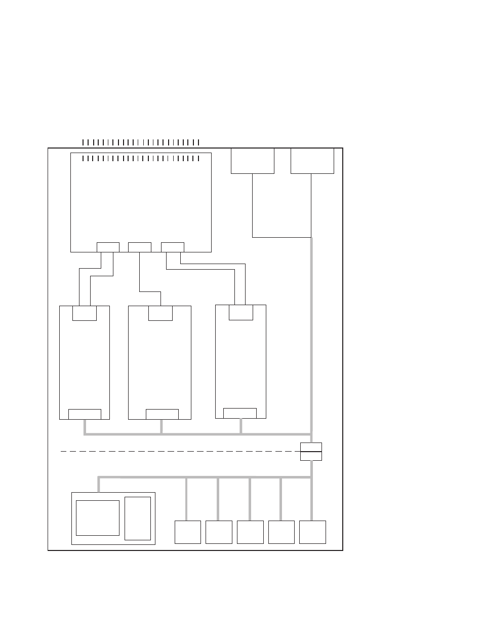
FRUs include: Fans, circuit breaker/LED card, switch supervisor card, switch power card(s),
inner chassis cable, front chassis cable, complete assembly.
SPS-8 There are only 8 ports. All clocks are distributed through data cables.
FRUs include: Fans, circuit breaker/LED card, switch supervisor card, switch power card(s),
inner chassis cable, front chassis cable, complete assembly.
----
----
----
----
----
----
----
----
----
----
----
----
----
----
----
----
----
----
----
----
----
----
----
----
----
----
----
----
----
----
----
----
----
----
----
----
----
----
----
----
----
----
----
----
----
----
----
----
(On external bulkhead)
(On planar)
J34
J1
J32
J3
J4
J31
J33
J2
J1
J2
P1
P2
Supervisor
bus card
+48 V dc
+12 V dc
Switch planar
J35
J34
J33
+5 V dc
-5 V dc
+5 V dc
-5 V dc
Switch power
supply 2
Switch
supervisor
card
Switch power
supply 1
P6
P6
P5
P5
P4
P4
Inner
chassis
cable
Cup
guide
Front
chassis
cable
P3
P3
P 2
P1
P9
P8 P7
LEDs
Green
Yellow
CB
Fan
5
Fan
4
Fan
3
Fan
2
Fan
1
Figure 1-1. SP Switch high-level diagram
Switch description and problem determination (MAP 0590)
1-2
RS/6000 SP: SP Switch Service Guide